Electric core transfer box and using method thereof

A turnover box and cell technology, applied to rigid containers, containers, packaging, etc., can solve the problems of low production efficiency, waste of labor, inconvenience, etc., and achieve the effects of convenient inventory, improved transfer efficiency, and space saving

Inactive Publication Date: 2018-07-03
江西省汇亿新能源有限公司
View PDF6 Cites 2 Cited by
  • Summary
  • Abstract
  • Description
  • Claims
  • Application Information

AI Technical Summary

Problems solved by technology

The currently used turnover box, such as a cylindrical battery turnover box disclosed by the patent No. CN201520326954.1, includes a box body with an open top, and two opposite side surfaces at the top of the box body are provided with pin holes respectively. The box body is provided with multiple layers of intermediate plates parallel to each other. Slots are arranged on two opposite side surfaces of the intermediate plates. The positions of the slots correspond to the positions of the pin holes. Both upper and lower s

Method used


Image

  • Electric core transfer box and using method thereof
  • Electric core transfer box and using method thereof
  • Electric core transfer box and using method thereof

Examples


Embodiment 1

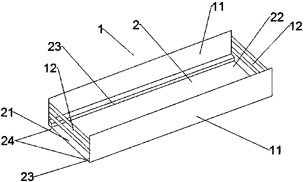
[0042] The battery turnover box of this embodiment, such as figure 1 As shown, it includes a turnaround box main frame 1 and a pumping plate 2. The turnaround box main frame 1 includes two relatively parallel side plates 11 and fixed brackets 12 that fix the side plates 11 at both ends of the two side plates 11, The distance between the two side plates 11 matches the distance between the two ends of the positive and negative tabs of the cell, and the pumping plate 2 is slidably connected to the two side plates 11; the pumping plate 2 includes an extraction end 21 and an insertion end 22 , the two ends of the connection between the pumping plate 2 and the side plate 11 are respectively provided with limit bars 23, the distance between the two limit bars 23 matches the length of the battery cell, and a limit bar is formed between the two limit bars. Groove 24, the turnover box main frame 1 and the pumping plate 2 form a space for placing batteries, and the depth of the space for...

Embodiment 2

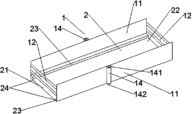
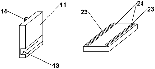
[0049] The battery turnover box of this embodiment, such as figure 2 and image 3 As shown, it includes the turnover box main frame 1 and the pumping plate 2. The turnover box main frame 1 includes two relatively parallel side plates 11 and fixed brackets 12 that fix the side plates 11 at both ends of the two side plates 11, The distance between the two side plates 11 matches the distance between the positive and negative tabs of the cell. The bottom of the side plates 11 is provided with a slide rail 13 that matches the pumping plate 2. The pumping plate 2 passes through the The slide rail 13 is slidably connected with the two side plates 11 and can be easily separated. The pumping plate 2 includes an extracting end 21 and an inserting end 22. The two ends of the pumping plate 2 connected to the side plate 11 are respectively provided with limiting strips 23, and the limiting strips 23 are made of elastic materials. It is more convenient to put it in, and it will not damag...

Embodiment 3

[0057] The battery turnover box of this embodiment, such as Figure 4 and Figure 5 As shown, it includes a turnaround box main frame 1 and a pumping plate 2. The turnaround box main frame 1 includes two relatively parallel side plates 11 and fixed brackets 12 that fix the side plates 11 at both ends of the two side plates 11, The distance between the two side plates 11 matches the distance between the positive and negative tabs of the battery cell. The pumping plate 2 is provided with a slide rail 25 that matches the side plate 11. The pumping plate 2 passes through the sliding rail 25. The rail 25 is slidably connected with the two side plates 11 and can be easily separated. The pumping plate 2 includes an extracting end 21 and an inserting end 22, and the two ends of the pumping plate 2 connected to the side plate 11 are respectively provided with limiting strips 23, the limiting strips 23 are made of elastic materials, and the battery cells It is more convenient to put i...


PUM


Abstract

The invention provides an electric core transfer box and a using method thereof. The electric core transfer box comprises a transfer box main frame and pulling plates, the transfer box main machine frame comprises two side plates which are relatively parallel, and fixed supports which are positioned at the two ends of the two side plates and used for fixing the side plates; the pulling plates areconnected with the two side plates in a sliding mode; each pulling plate comprises a pulling end and an insertion end, and limiting strips are arranged at the two ends, connected with the side plates,of the pulling plates; the distance between the two limiting strips is matched with the length of the electric core, and a limiting groove is formed between the two limiting strips; and the transferbox main machine frame and the pulling plates form a space for containing the electric core. According to the electric core transfer box, the pulling plates are matched with the transfer box main frame, the process that one electric core is taken out from the electric core transfer box and then put into the conveying belt is omitted, and the production efficiency is improved; the electric core transfer box can be stacked together, so that the space is saved; the electric core can be well fixed, and the requirements of enterprise safety production are met; and the use method is simple, the operation difficulty is avoided, and the method can be applied to large-scale production.

Description

technical field [0001] The invention relates to the technical field of cylindrical battery storage and shipment, in particular to a battery turnover box and a use method thereof. Background technique [0002] Because of its high energy, high battery voltage, wide operating temperature range, and long storage life, lithium batteries have been widely used in military and civilian small electrical appliances, such as mobile phones, portable computers, video cameras, cameras, etc., in electric vehicles, There are also good application prospects in artificial satellites, aerospace and energy storage. [0003] Lithium batteries usually come in two shapes: cylindrical and square. At present, the battery cores of cylindrical lithium batteries at home and abroad are usually coiled lithium battery cores. The preparation process of the battery cores is as follows: firstly, special solvents and adhesives are used to mix the active materials of the positive and negative electrodes respe...

Claims


Application Information

Patent Timeline
IPC IPC(8): B65D25/10B65D21/032
CPCB65D25/10B65D21/0209
Inventor 廖宗江吴忠明
Owner 江西省汇亿新能源有限公司
Why Eureka
Try Eureka