Gradient coil using composite cooling water pipe

A technology of gradient coils and cooling water pipes, applied in the field of gradient coils and MRI gradient coils, can solve problems such as increasing water leakage, not considering process difficulties, and affecting heat dissipation effects, so as to ensure temperature stability, reduce the risk of water leakage, and ensure uniformity Effect

Pending Publication Date: 2018-07-03
HUNAN MAGTECH MEDICAL TECH CO LTD
View PDF1 Cites 4 Cited by
  • Summary
  • Abstract
  • Description
  • Claims
  • Application Information

AI Technical Summary

Problems solved by technology

[0003] The existing traditional gradient coil structure uses the hollow Z main coil and Z shielding coil as the cooling channel. In order to reduce the influence of eddy current, the diameter of the coil should not be too large, which will affect the heat dissipation effect. If different connection methods are used to meet the heat dissipation requirements , will form too many joints, increasing the probability of water leakage. At the same time, the biggest problem of this coil is that it cannot realize the separation of water and electricity. To ensure the safety of patients, deionized water must be used, which increases the difficulty and cost of maintenance.
The patent is ZL201420289868.3 "An Active Shielding Gradient Coil Structure". The structure proposed in this patent improves the heat dissipation capability of the gradient coil by sacrificing the performance of a part of the Z coil. However, this design does not consider many technological difficulties in the manufacturing process. Consider the user's requirements for radio frequency shielding and shimming space, as well as the impact of the coil based on this structure on the uniformity of the magnetic field

Method used


Image

  • Gradient coil using composite cooling water pipe
  • Gradient coil using composite cooling water pipe
  • Gradient coil using composite cooling water pipe

Examples


Embodiment Construction

[0019] In order to make the object, technical solution and advantages of the present invention clearer, the present invention is described below through specific embodiments shown in the accompanying drawings. It should be understood, however, that these descriptions are illustrative only and are not intended to limit the scope of the present invention. Also, in the following description, descriptions of well-known structures and techniques are omitted to avoid unnecessarily obscuring the concept of the present invention.

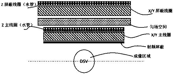
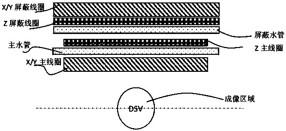
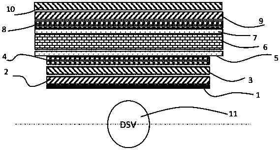
[0020] Such as Figure 1-7 As shown, a gradient coil using a composite material cooling water pipe in this embodiment includes a gradient coil main body, and the structure of the upper half of the axial section of the gradient coil main body is as follows image 3 As shown, the lower half is symmetrical to its axial direction, and the coil body is sequentially composed of a radio frequency shielding layer 1, a main coil part, a main water pipe 5, a shimmin...


PUM


Abstract

The invention discloses a gradient coil using a composite cooling water pipe. The gradient coil using the composite cooling water pipe comprises a gradient coil main body, wherein the coil main body is sequentially composed of a radio frequency shielding layer, a main coil part, a main water pipe, a uniform field space, a shielding water pipe and a shielding coil part from inside to outside; the main coil part is composed of an X coil, a Y coil and a Z coil in a stacking manner from inside to outside, the shielding coil part is composed of a Z shielding coil, an X shielding coil and a Y shielding coil in the stacking manner from inside to outside, the structure gives consideration to balance in performances of the X, Y and Z coils, the composite cooling water pipe is used, thermal conductivity of a cooling system is improved, and the uniform field space is located in a water cooling system, so that temperature stability of a uniform field material is guaranteed, and uniformity of a magnetic field is guaranteed.

Description

Technical field: [0001] The invention belongs to the technical field of MRI gradient coils, in particular to a gradient coil using composite cooling water pipes. Background technique: [0002] The gradient coil is one of the core components of the MRI (Magnetic Resonance Imaging, English full name: Magnetic Resonance Imaging) system, which mainly realizes frequency encoding, phase encoding and layer selection during the MRI scanning process. [0003] The existing traditional gradient coil structure uses the hollow Z main coil and Z shielding coil as the cooling channel. In order to reduce the influence of eddy current, the diameter of the coil should not be too large, which will affect the heat dissipation effect. If different connection methods are used to meet the heat dissipation requirements , will form too many joints, increasing the probability of water leakage. At the same time, the biggest problem of this coil is that it cannot realize the separation of water and ele...

Claims


Application Information

Patent Timeline
Patent Type & Authority Applications(China)
IPC IPC(8): G01R33/385G01R33/38G01R33/421G01R33/422
CPCG01R33/3856G01R33/3804G01R33/4215G01R33/422
Inventor 赵华炜赫克托耳·桑切斯·洛佩兹王鹏
Owner HUNAN MAGTECH MEDICAL TECH CO LTD
Why Eureka
Try Eureka