
Head-up display device for remote image displaying

A head-up display, long-distance technology, applied in optical components, optics, instruments, etc., can solve the problems of short images, dizziness for drivers, affecting driving safety, etc., and achieve the effect of long light path distance

Inactive Publication Date: 2018-07-03
E LEAD ELECTRONICS
View PDF16 Cites 6 Cited by
  • Summary
  • Abstract
  • Description
  • Claims
  • Application Information

AI Technical Summary

Problems solved by technology

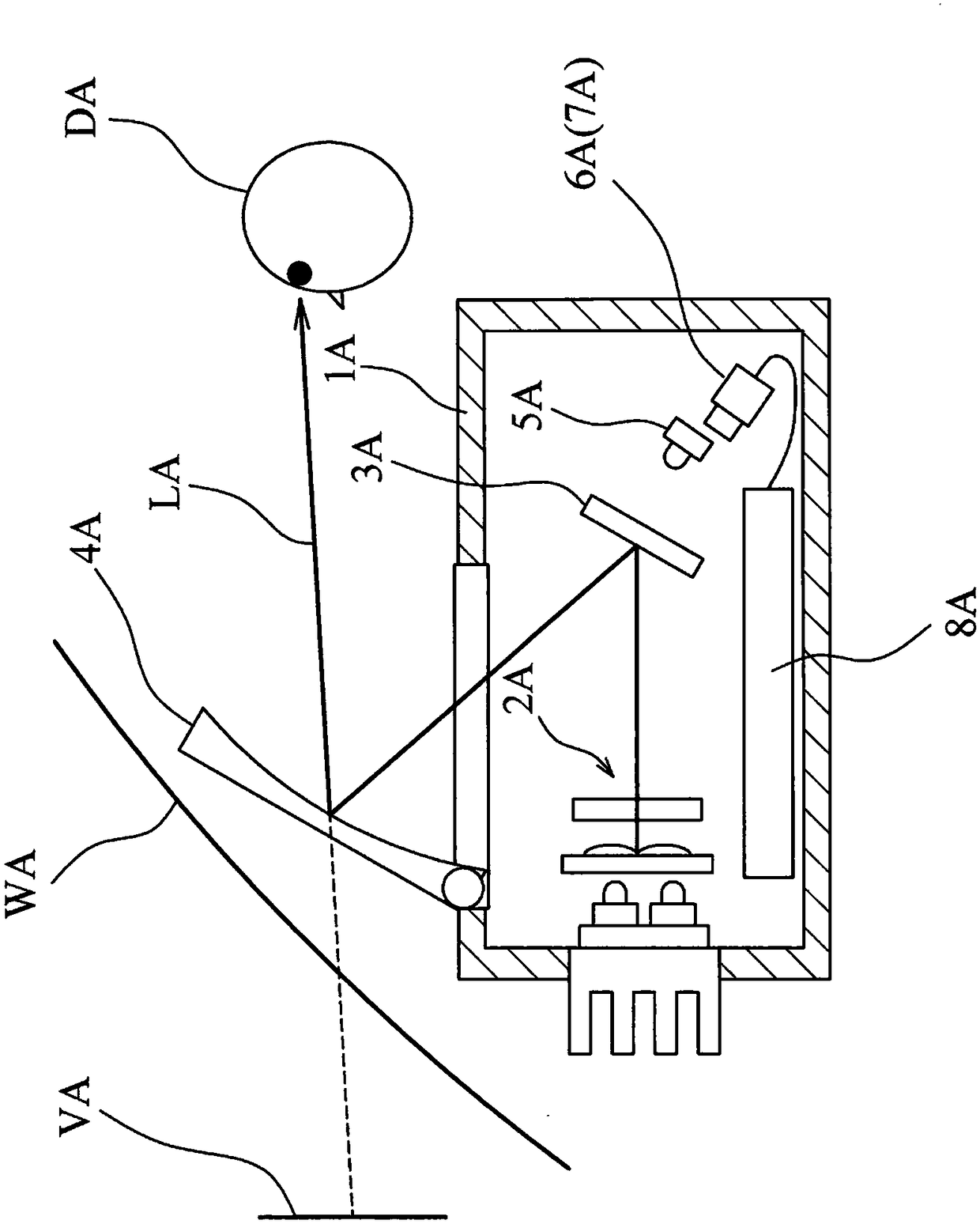
[0008] 1. In the above-mentioned prior patents, some of them use a single projection device to project vertical cutting images, but the disadvantage is that the projected standard distance images are too short, and the driver is prone to visual dizziness when watching, which affects to driving safety
[0009] 2. Although some prior patents can project standard-distance images and longer-distance images through two or more projection devices, or with more cutting screens, most of the multiple projection devices are located at the same position. Most of the images provided are horizontal cutting images on the same horizontal plane, and there are few vertical cutting images, so it is not easy to accurately paste the navigation guidance symbols directly on the road or on the rear of the front car to be warned, so that the navigation guidance The effect is greatly reduced

Method used


Image

  • Head-up display device for remote image displaying
  • Head-up display device for remote image displaying
  • Head-up display device for remote image displaying

Examples


no. 1 example

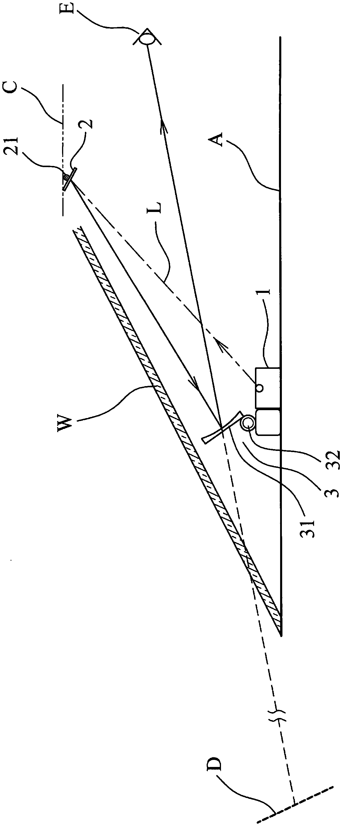
[0037] Such as figure 2 Shown is the first embodiment of the remote display head-up display device provided by the present invention, including:

[0038] An image projection module 1 is arranged above the instrument panel A below the windshield W of a vehicle, and projects an image. The image projection module 1 is a digital light processing device (Digital Light Processing, abbreviated as DLP, the image The projection device 1 is to utilize a kind of imaging technology used in projectors and rear projection televisions);

[0039] A reflective diffuser 2 is arranged at the junction of the roof C of the vehicle and the windshield W, the light path L of the output light source of the image projection module 1 is projected to the reflective diffuser 2, and 2, making the reflective diffuser 2 a screen for displaying images. The reflective diffuser 2 also includes a rotating shaft 21, and the position of the image projected on the bottom of the windshield W can be adjusted by rot...

no. 2 example

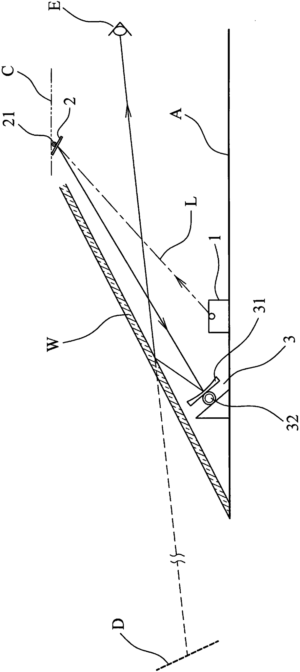
[0045] Such as Figure 6 Shown is the second embodiment of the remote display head-up display device provided by the present invention, including:

[0046] An image projection module 1 is arranged under the instrument panel A under the windshield W of a vehicle, and projects an image light source. The image projection module 1 is a digital light processing device (Digital Light Processing, abbreviated as DLP, which Image projection device 1 utilizes a kind of imaging technology used in projectors and rear-projection televisions);

[0047] A reflective diffusion sheet 2 is arranged at the junction of the roof C of the vehicle and the windshield W. The light path L of the output image light source of the image projection module 1 is directed to the reflective diffusion sheet 2, and Imaging on the sheet 2 makes the reflective diffuser 2 a screen for displaying images. The reflective diffuser 2 also includes a rotating shaft 21, and the position of the image projected on the bott...


PUM


Abstract

The invention discloses a head-up display device for remote image displaying. The head-up display device comprises an image projection module, a reflective diffusion sheet and a concave mirror module.On the basis of cooperation of the reflective diffusion sheet and the concave mirror module, the reflection distance is increased to obtain a long optical path distance. A virtual image at a long projection distance can be obtained under the same concave mirror amplification factor, so that the visual dizzy feeling of the driver is reduced and the optimal visual effect is obtained and thus the driving safety is enhanced.

Description

technical field [0001] The invention relates to a head-up display device for long-distance imaging, especially a head-up display device that can reduce the driver's visual dizziness. It uses a reflective diffuser and a concave mirror module to increase the reflection distance to obtain a longer distance. With a long optical distance, a virtual image with a longer projection distance can be obtained under the same magnification of the concave mirror, so as to reduce the driver's visual dizziness and obtain the best visual effect, thereby improving driving safety. Background technique [0002] At present, the HUD technology used in automobiles is not as complicated as that used in aircraft; it is an optical system, generally composed of two main devices: a projector and an image mirror. The projector is composed of a signal light source, a The projection mirror is composed of other optical components. The signal light source of the projector is composed of an LCD liquid crysta...

Claims


Application Information

Patent Timeline
IPC IPC(8): G02B27/01
CPCG02B27/0101
Inventor 陈锡勋
Owner E LEAD ELECTRONICS
Learn More