Vacuum explosion chamber with static side buffer and direct current circuit breaker

A technology of vacuum interrupter and static side contacts, which is applied in the field of high voltage devices, can solve the problems of reduced service life and extra impact force of opening, and achieve the effects of improving service life, reducing contact deformation and avoiding damage

Inactive Publication Date: 2018-07-03
ELECTRIC POWER RESEARCH INSTITUTE, CHINA SOUTHERN POWER GRID CO LTD +3
View PDF8 Cites 3 Cited by
  • Summary
  • Abstract
  • Description
  • Claims
  • Application Information

AI Technical Summary

Problems solved by technology

[0007] The invention provides a vacuum interrupter and a DC circuit breaker with static side buffer, which solves the problem that the existing DC circuit breaker adopts the closing buffer mechanism, which still introduces extra impact force when opening the switch, resulting in reduced service life, etc. question

Method used


Image

  • Vacuum explosion chamber with static side buffer and direct current circuit breaker
  • Vacuum explosion chamber with static side buffer and direct current circuit breaker
  • Vacuum explosion chamber with static side buffer and direct current circuit breaker

Examples


Embodiment 1

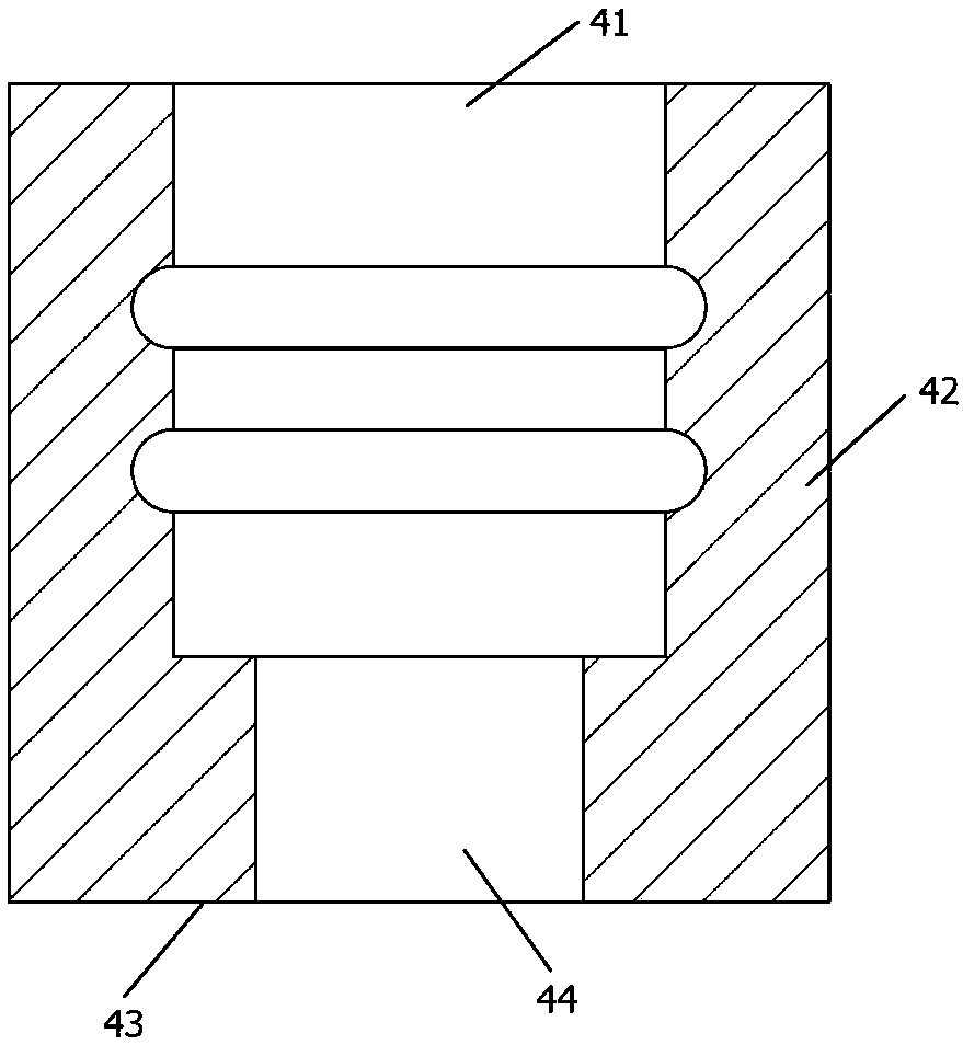
[0030] Example one, as image 3 and 4 As shown, the cross section of the conductive block 4 is a U-shaped structure, of course, it can also be other shapes, such as square, trapezoid, etc., including an opening 41, a side wall 42 and a bottom surface 43, the opening 41 is connected to the housing 1, and the bottom surface The center of 43 is provided with a through hole 44. The static conductive rod 7 has a T-shaped structure as a whole, including a vertical portion 71 and a horizontal portion 72. One end of the vertical portion 71 is connected to the static side contact, and the other end passes through the through hole. 44 is connected with the horizontal part 72, the horizontal part 72 is connected with the side wall 42 through the conductive contact fingers 6, the diameter of the through hole is larger than the diameter of the vertical part and smaller than the diameter of the horizontal part, so that the horizontal part 72 is easy to be stuck between the two holes of the ...

Embodiment 2

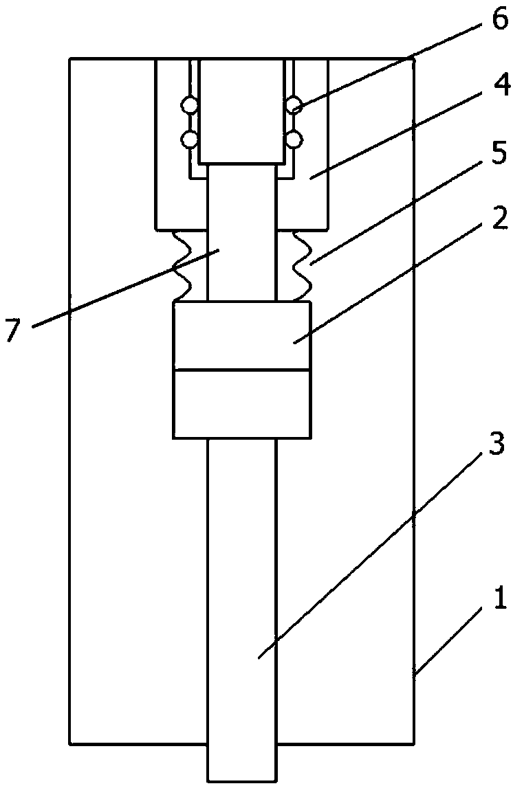
[0031] Example two, as Figure 7 and 8 As shown, the cross section of the conductive block 4 is a U-shaped structure, including an opening 41, a side wall 42 and a bottom surface 43, the opening 41 is connected with the housing 1, and a through hole 44 is provided in the center of the bottom surface 43. The static conductive rod 7 The other end of the static conductive rod 7 is provided with a long waist hole 73 along the length direction, the side wall 42 of the conductive block 4 is provided with a first through hole 45, the other end of the static conductive rod 7 and the side wall of the conductive block 4 also pass through the cylindrical pin 8. The long waist hole 73 is connected to the first through hole 45 , the closing stopper is set at the top of the long waist hole 73 , and the opening stopper is set at the top of the long waist hole 73 . In this way, the static conducting rod 7 It is not necessary to adopt a T-shaped structure, and a straight rod shape can also be...


PUM


Abstract

The invention relates to the technical field of high-voltage devices, and discloses a vacuum explosion chamber with a static side buffer, comprising a casing of the vacuum explosion chamber. The interior of the casing is provided with a static side contact and a moving side contact from top to bottom. A buffering conductive component is disposed between the static side contact and the casing, andthe buffering conductive component is used for buffering rigid contact between the static side contact and the movable side contact when closing, and does not create additional impact when breaking. Adirect current circuit breaker is also disclosed, including the vacuum explosion chamber described above. The vacuum explosion chamber and the direct current circuit breaker of the invention are simple, reliable, and easy to apply, and have good marketing value.

Description

technical field [0001] The invention relates to the technical field of high-voltage devices, in particular to a vacuum interrupter with static side buffer and a DC circuit breaker. Background technique [0002] When the DC circuit breaker adopts the vacuum switch as the mechanical switch, the mechanical switch uses the vacuum as the insulating medium and the arc extinguishing medium to realize the functions of closing, carrying and breaking the current under normal or abnormal circuit conditions. The vacuum circuit breaker is mainly composed of the operating mechanism (the mechanical switch of the vacuum DC circuit breaker generally adopts the repulsion mechanism) and the vacuum interrupter. [0003] During the closing process, pre-breakdown and arcing will occur when the contacts approach, increasing the possibility of contact fusion welding. If the closing speed of the contacts is increased blindly in order to reduce the arcing time, due to the large quality of the contac...

Claims


Application Information

Patent Timeline
Patent Type & Authority Applications(China)
IPC IPC(8): H01H33/664H01H3/60
CPCH01H33/664H01H3/60
Inventor 陈名黎小林张祖安程小明罗敏侯斌李艳林朱青
Owner ELECTRIC POWER RESEARCH INSTITUTE, CHINA SOUTHERN POWER GRID CO LTD
Why Eureka
Try Eureka