Injection mold for producing sewage treatment pipe

A technology for producing sewage and injection molds, applied in the field of molds, can solve the problems of increasing the structural size of the mold, the space in the middle is not fully utilized, and the cost of single mold manufacturing of the mold is increased. The effect of reducing the cost of single-piece manufacturing

Inactive Publication Date: 2018-07-06
乌鲁木齐九品芝麻信息科技有限公司
0 Cites 4 Cited by

AI-Extracted Technical Summary

Problems solved by technology

[0002] In the manufacturing process of sewage treatment pipes, injection molds are often used for manufacturing and molding. In the thread-removing mechanism of injection molds, if the mold space structure is relatively narrow and the product requires a multi-cavity layout, rack drives are used to perform thread removal. One will increase...

Abstract

The invention provides an injection mold for producing a sewage treatment pipe. The injection mold comprises a central worm driving type gear de-threading mechanism, a threaded core rotating assemblyand a worm driving assembly; the central worm driving type gear de-threading mechanism aims at solving the technical problem that because the narrow space in a multi-cavity de-threading die gear de-threading mechanism cannot be fully utilized, the cost of single-mold manufacturing is increased, and has the beneficial effects that the that the problem that the internal thread demolding wrapping force of the product is difficult to fall off is solved. The injection mold has the beneficial effects that the demolding of threads is separated through the rotation of a threaded core, the demolding ofa product is performed by pushing an ejector rod and a push pipe on the outer circle of the thread, the thread is free of deformation, and the demolding action is reliable.

Technology Topic

Worm driveEngineering +3

Image

  • Injection mold for producing sewage treatment pipe
  • Injection mold for producing sewage treatment pipe
  • Injection mold for producing sewage treatment pipe

Examples

  • Experimental program(1)

Example Embodiment

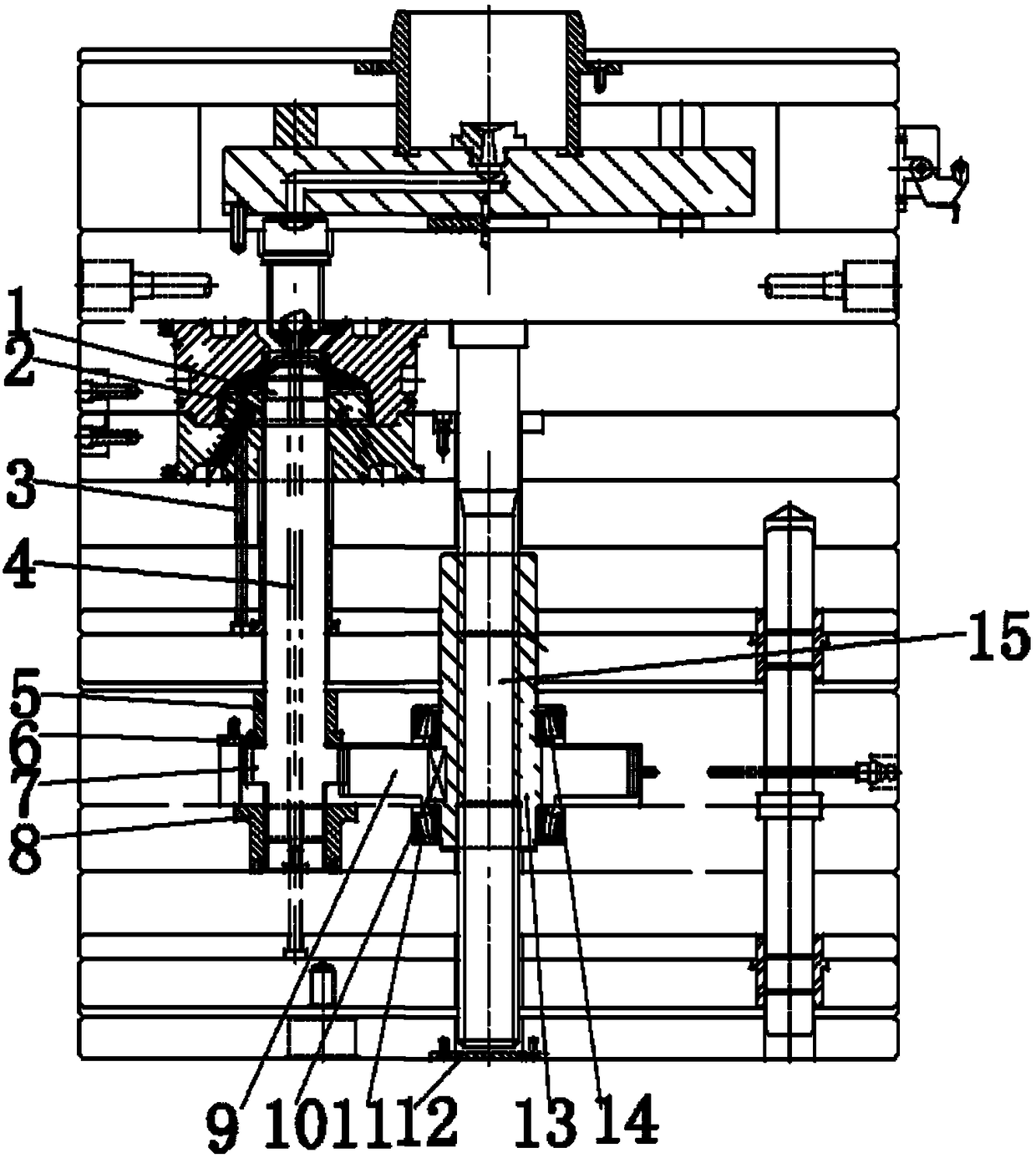
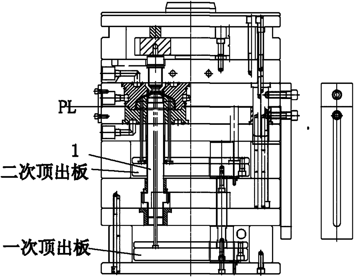
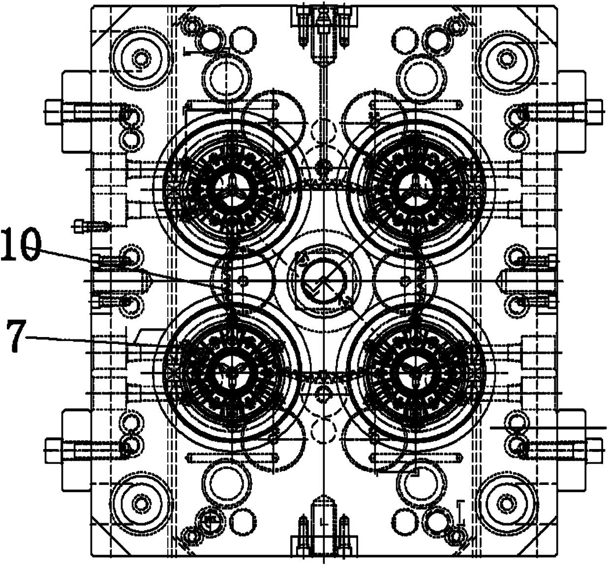
[0017] Figure 1-4 Shown is the relevant explanatory diagram of the present invention; the specific embodiment is, as figure 1 , figure 2 , image 3 , Figure 4 As shown in the figure, an injection mold for producing sewage treatment pipes includes a central worm-driven gear de-threading mechanism, which includes a central threaded core 1, an inner edge ejecting a push tube 2, an auxiliary ejecting needle 3, and a de-threading mechanism. Material ejector 4, upper rotating sleeve 5, rotating sleeve fixing plate 6, threaded core gear 7, lower threaded sleeve 8, worm sleeve driving gear 9, gear key 10, lower bearing 11, ground cover 12, worm sleeve 13, Upper bearing 14, central drive worm 15.
[0018] The threaded core rotating assembly of the mechanism includes a central threaded core 1, an inner edge ejection push tube 2, an auxiliary ejection pin 3, a stripping ejector 4, an upper rotating sleeve 5, a rotating sleeve fixing plate 6, and a threaded core. Gear 7, lower threaded sleeve 8, worm sleeve drive gear 9; the central thread core 1 is the internal thread forming part of the product, the upper end of which is sleeved in the inner edge of the ejection push tube 2, and the lower end passes through the upper rotating sleeve 5 and the lower threaded sleeve 8 is installed on the mold base template of the mold; the inner edge ejection push tube 2 is a thin-walled annular formed part with an internal thread of the product, the upper end of which is sleeved in the core insert of the mold forming part, and the lower end is installed in the first ejection of the mold It plays the role of ejecting the thin-walled ring of the product; the auxiliary ejector pin 3 is installed on the first ejection plate of the mold, and plays the role of assisting the inner edge to eject the push tube 2; the ejector pin 4 It is sleeved on the center of the central thread core 1, and the lower end is installed on the second ejection plate of the application mold, which plays the role of cutting and ejecting the waste of the runner of the product; the upper rotating sleeve 5 is sleeved on the central thread core 1. on the upper end of the threaded core gear 7, and its outer end is fixedly installed on the template of the mold through the rotating sleeve fixing plate 6, so as to limit the upward movement of the threaded core gear 7; the threaded core gear 7 passes through The pin is fastened on the central threaded core 1, and is used to transmit the power of the worm sleeve drive gear 9 to the central threaded core 1; The outer end is installed on the mold template, which is used for the up and down movement guidance of the central thread core 1, and provides guidance for the smooth rotation of the central thread core 1; the thread core gear 7 and the worm sleeve drive gear 9 are geared.
[0019] The worm drive assembly of the mechanism includes a worm sleeve drive gear 9, a gear key 10, a lower bearing 11, a ground cover 12, a worm sleeve 13, an upper bearing 14, and a central drive worm 15; the worm sleeve drive gear 9 is sleeved on the worm sleeve 13. , and the twisting of the worm sleeve 13 is transmitted through the gear key 10; the upper end of the worm sleeve 13 is sleeved with a bearing 14, and the lower end is sleeved with a lower bearing 11. The sleeve 13 and the central driving worm 15 are installed in cooperation with the worm drive; the upper end of the central driving worm 15 is installed on the fixed mold side of the mold, and the worm sleeve 13 is installed on the movable mold side of the mold. The central driving worm 15 is used to drive the worm sleeve 13 to drive the worm sleeve to drive the gear 9, so as to achieve the purpose of driving the threaded core gear 7.
[0020] In the described mechanism, the threaded core rotating assembly is installed on the movable mold side of the applied object mold, and in the worm drive assembly, except for the central drive worm 15 installed on the fixed mold side, the other components are installed on the movable mold side of the mold. side.
[0021] In the mechanism, the threaded core rotating assembly corresponds to the forming and unthreading of one mold and one cavity of the product, and the worm drive assembly can meet the requirement of one drive for multiple. .
[0022] The use method of the central worm-driven gear de-threading mechanism includes the following steps:
[0023] In actual work, the organization's work process is divided into the following steps:
[0024] 1) The mold is opened at the PL parting surface, and the product is demolded from the cavity surface; during the opening process, the movable mold of the mold retreats, the worm sleeve (13) goes down, and the worm sleeve (13) is driven by the central worm (15) during the downward process. ) to rotate, thereby driving the worm sleeve drive gear (9) to rotate, the worm sleeve drive gear (9) drives the threaded core gear (7), the central thread core (1) to rotate, and the central thread core (1) is in the bottom Under the guidance of the threaded sleeve (8), the thread is matched and rotated, so that the threaded core at the upper end thereof is separated from the product.
[0025] 2) After the ejection and unthreading of the product is completed, the ejector rod of the injection molding machine drives the primary ejector plate and the secondary ejector plate to move up, thereby driving the inner edge to eject the ejector tube (2), the auxiliary ejector needle (3), and the ejector ejector. The rod (4) pushes out the product and runner waste from the core synchronously,
[0026] To achieve the purpose of completely demoulding the product.
[0027] The specific embodiments described herein are only for illustrating the spirit of the present invention, and those skilled in the art to which the present invention pertains can make various modifications or supplements to the specific embodiments described, or use similar ways to replace, but without departing from the spirit or scope of the invention as defined by the appended claims.

PUM

no PUM

Description & Claims & Application Information

We can also present the details of the Description, Claims and Application information to help users get a comprehensive understanding of the technical details of the patent, such as background art, summary of invention, brief description of drawings, description of embodiments, and other original content. On the other hand, users can also determine the specific scope of protection of the technology through the list of claims; as well as understand the changes in the life cycle of the technology with the presentation of the patent timeline. Login to view more.

Similar technology patents

Compound cycloidal reducer

PendingCN107882928AGuaranteed machinabilitySmall structure size
Owner:CHONGQING UNIV

Illumination system and method for producing light-beam with required form

InactiveCN1354340AImprove efficiencySmall structure size
Owner:KONINKLIJKE PHILIPS ELECTRONICS NV

Artificial surface plasmon transmission line based on fractal branch structure and its application thereof

PendingCN110581333AStrong electromagnetic wave binding performanceSmall structure size
Owner:XIAMEN UNIV +1

Electronic throttle valve device with vanes rotating through arc rack

PendingCN113513414ASmall structure sizerotation stabilization
Owner:HUBEI UNIV OF AUTOMOTIVE TECH

Classification and recommendation of technical efficacy words

  • Small structure size
  • Reduce manufacturing difficulty

Mobile phone antenna with reconfigurable directional diagram

InactiveCN103346392ASimple structureSmall structure size
Owner:HARBIN ENG UNIV

Transmission type polarized transition super surface

ActiveCN107565224ASmall structure sizeSimple structure
Owner:FUDAN UNIV

Industrial heat-resisting fireproofing instrument cable and manufacturing technology thereof

ActiveCN103345964ASmall structure sizeGood mechanical and electrical properties
Owner:安徽虹都电缆集团有限公司

Large suspension kiln and production process thereof

ActiveCN106568331Areduce gas flowSmall structure size
Owner:ACRE COKING & REFRACTORY ENG CONSULTING CORP DALIAN MCC

Vertical polarization C-waveband broadband short backfire antenna

ActiveCN105514584ASmall structure sizeBroaden the working frequency band
Owner:XIAN AISHENG TECH GRP +1

Technique for electrolysis processing fine slits and its devices

InactiveCN1445040AReduce manufacturing difficultyReduction of stray corrosion
Owner:NANJING UNIV OF AERONAUTICS & ASTRONAUTICS

Magnet retaining relay

Owner:XIAMEN HONGFA ELECTROACOUSTIC CO LTD

Manufacturing and overturning device for heat exchanger tube bundle assembly

PendingCN108213887AAvoid set difficultiesReduce manufacturing difficulty
Owner:HARBIN ELECTRIC CORP QINHUANGDAO HEAVY EQUIP

Flexible ironing groove structure of groove type ironing machine

ActiveCN104018329AReduce manufacturing difficultyAchieve machine flexibility
Owner:SHANGHAI WEISHI MACHINERY
Why Eureka
Try Eureka