
Loader traction device for dragging flat car

A technology for traction devices and loaders, applied in traction connectors, vehicle parts, transportation and packaging, etc., can solve the problems of inconvenient connection between loaders and flatbed vehicles, no buffer structure, and easily damaged devices, etc., and achieve simple structure, Convenient and quick connection, prolonging the service life effect

Active Publication Date: 2018-07-06
万静琼
View PDF5 Cites 12 Cited by
  • Summary
  • Abstract
  • Description
  • Claims
  • Application Information

AI Technical Summary

Problems solved by technology

It can be known from the above technical solution that the flatbed truck and the loader are connected through the traction front bracket and the steering joint, which can realize the function of the loader dragging the flatbed truck, and can ensure that the traction front bracket can be adjusted when the loader pulls the flatbed truck up and downhill. The force direction of the loader reduces the requirements on the road surface when the loader tows the flatbed truck, and truly realizes the purpose of one machine with multiple functions, but it is not convenient to connect the loader and the flatbed truck in actual use, which brings inconvenience to people's use, and it does not have Buffer structure, when the loader starts and stops, it is easy to damage the device, so we urgently need an easy-to-use and self-protecting loader traction device for dragging flatbed vehicles to solve the above problems

Method used


Image

  • Loader traction device for dragging flat car
  • Loader traction device for dragging flat car
  • Loader traction device for dragging flat car

Examples


Embodiment Construction

[0024] The technical solutions in the embodiments of the present invention will be clearly and completely described below with reference to the accompanying drawings in the embodiments of the present invention. Obviously, the described embodiments are only a part of the embodiments of the present invention, but not all of the embodiments.

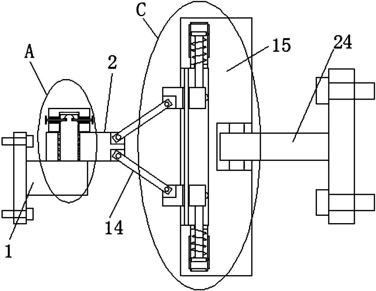
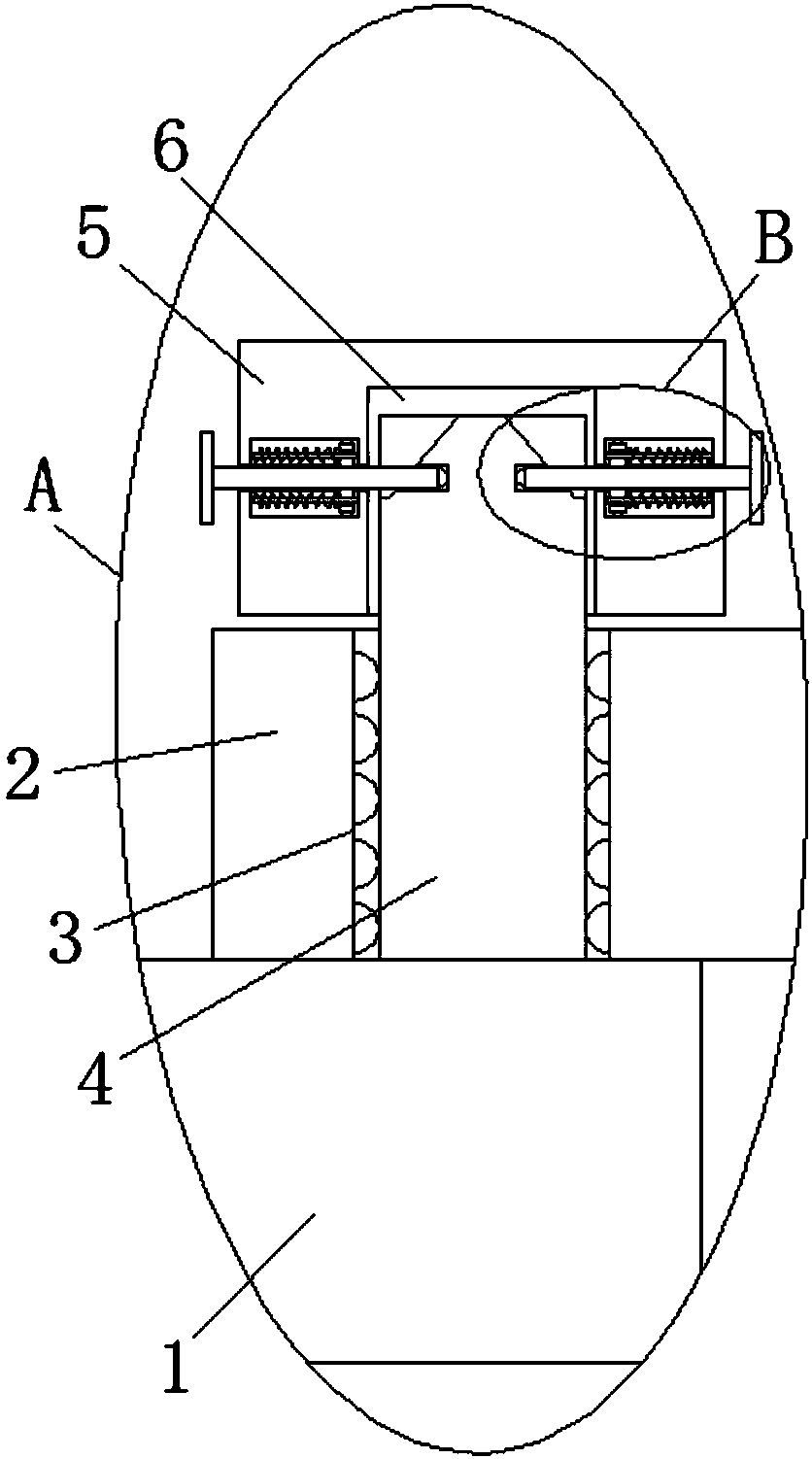
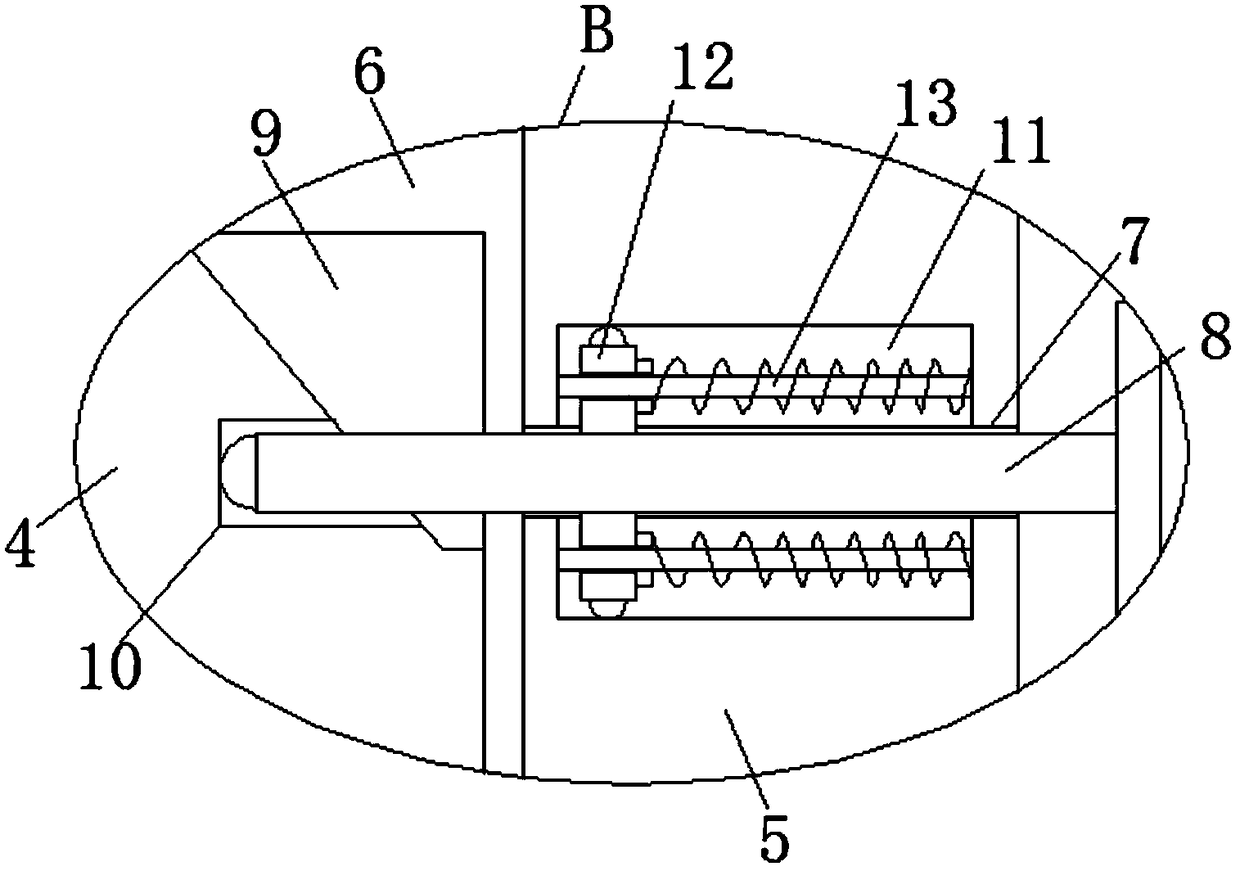
[0025] refer to Figure 1-5, a loader traction device for dragging a flatbed truck, comprising a fixed seat 1, a connecting block 2 is provided on the top of the fixed seat 1, a first through hole 3 is opened at the bottom of the connecting block 2, and the top of the fixed seat 1 is fixedly installed There is a fixed rod 4, the top of the fixed rod 4 runs through the first through hole 3, the top of the connecting block 2 is provided with a fixed block 5, the bottom of the fixed block 5 is provided with a first groove 6, and the top of the fixed rod 4 is slidably installed on the In a groove 6, a second through hole 7 is symmetrically open...


PUM


Abstract

The invention discloses a loader traction device for dragging a flat car. The device comprises a fixing seat, the top of the fixing seat is provided with a connecting block, the bottom of the connecting block is provided with a first through hole, the top of the fixing seat is fixedly provided with a fixing rod, the top end of the fixing rod penetrates through the first through hole, a fixing block is arranged at the upper portion of the connecting block, the bottom of the fixing block is provided with a first groove, the top end of the fixing rod is slidably arranged in the first groove, theinner walls of the two sides of the first groove are symmetrically provided with second through holes, each second through hole is internally and slidably provided with a clamping rod, the two ends ofeach clamping rod extend out of the corresponding second through hole, and the two sides of the fixing rod are symmetrically provided with wedge grooves, wherein the top of each wedge groove is provided with an opening. The loader traction device for dragging the flat car has the advantages that the structure is simple, the practicability is strong, the flat car and a loader can be conveniently and quickly connected, the loader traction device has better buffering performance, it can be effectively avoided that a pull rod is bent when the loader is started and stopped, and the service life ofthe pull rod is prolonged.

Description

technical field [0001] The invention relates to the technical field of traction equipment, in particular to a loader traction device for towing a flatbed vehicle. Background technique [0002] At present, existing loaders are mainly used for shoveling operations, and users ignore the function of using the loader to pull other machines. However, in some enterprises, in order to improve transportation efficiency, the load capacity of flatbed trucks often exceeds the design standard, which makes it difficult for ordinary tractors to drag and requires tractors with greater traction, which undoubtedly brings greater investment to enterprises. For this reason, using the existing loaders in the enterprise to realize the function of pulling flatbed vehicles has become an urgent problem to be solved. [0003] Patent No. 201710476472.8, a loader traction device for dragging a flatbed truck, discloses a loader traction device for dragging a flatbed truck, which includes a traction fro...

Claims


Application Information

Patent Timeline
Patent Type & Authority Applications(China)
IPC IPC(8): B60D1/24
CPCB60D1/249
Inventor 罗厚镇
Owner 万静琼
Learn More