
Device for measuring pressure of finite filling retaining wall under different displacement modes and testing method

A mode and displacement technology, applied in the test of infrastructure, construction, infrastructure engineering, etc., can solve the problems that do not meet this condition, such as foundation pit retaining wall in commercial intensive area and adjacent existing buildings (structures), The mountain retaining wall and the rock mass behind the wall, lack of calculation methods, etc., achieve the effect of compact structure, accurate measurement and convenient operation

Inactive Publication Date: 2018-07-06
CHANGAN UNIV
View PDF0 Cites 8 Cited by
  • Summary
  • Abstract
  • Description
  • Claims
  • Application Information

AI Technical Summary

Problems solved by technology

However, in actual engineering, the width of the soil behind the wall sometimes does not meet this condition. Whether the failure mode of the soil behind the wall and the distribution of earth pressure can still conform to the classic Rankine or Coulomb theory of earth pressure has become a matter of close attention.
There is still no recognized and reasonable calculation method for the calculation of the earth pressure of the limited soil behind the wall, so the problem of the earth pressure acting on the rigid retaining wall under the influence of different fill widths needs to be solved urgently
[0003] The existing studies are all theoretical analysis or numerical simulation for the calculation of the earth pressure of the limited soil behind the wall, and only theoretically clarified the difference between the earth pressure of the limited soil and the conventional earth pressure, which still needs to be verified by experiments or engineering measurements

Method used


Image

  • Device for measuring pressure of finite filling retaining wall under different displacement modes and testing method
  • Device for measuring pressure of finite filling retaining wall under different displacement modes and testing method
  • Device for measuring pressure of finite filling retaining wall under different displacement modes and testing method

Examples


Embodiment Construction

[0045] The present invention will be described in detail below in conjunction with the accompanying drawings and specific embodiments.

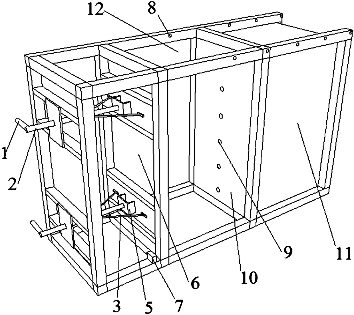
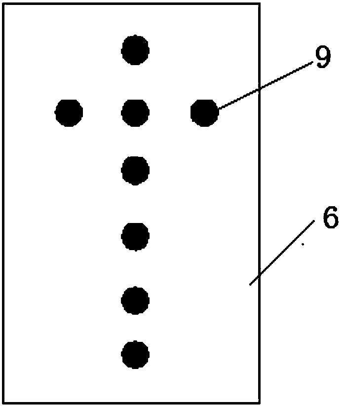
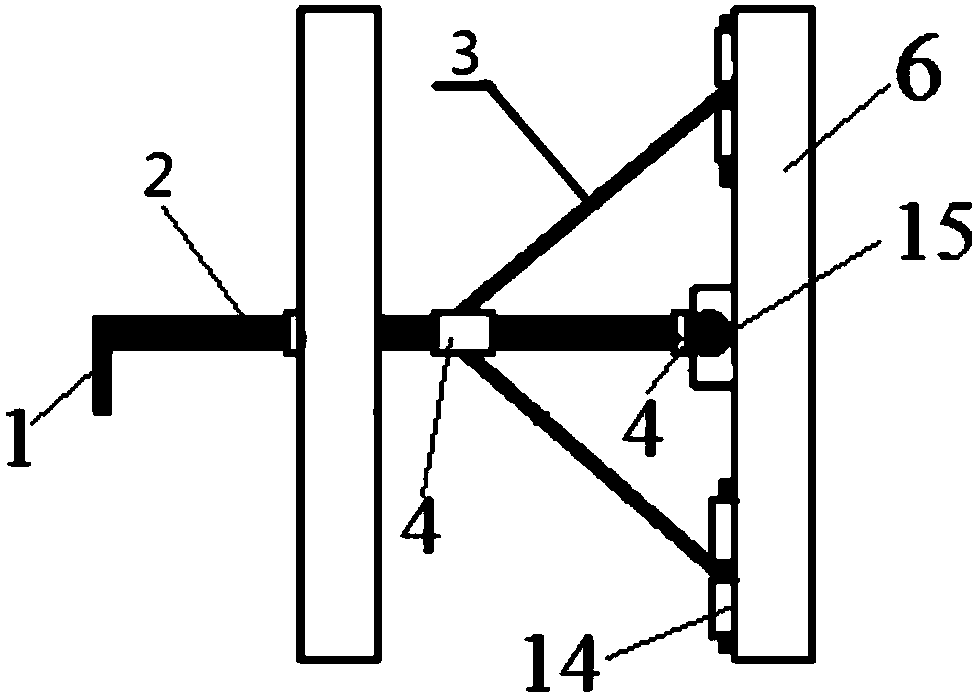
[0046] like figure 1 and figure 2 As shown, the present invention provides a kind of device for measuring the pressure of limited earth filling retaining wall in different displacement modes, comprising test box body 12 and box-shaped frame, test box body 12 comprising movable retaining wall 6 and fixed retaining wall 10, movable retaining wall 6. Screw rods 2 are connected to the upper and lower parts of the outer side. The upper and lower ends of the movable retaining wall 6 are also provided with a dial indicator 7 for detecting its movement. 12 The two side walls are rigid walls, and the rigid walls are fixedly connected with the box-shaped frame; the box-shaped frame is also provided with a fixing plate for fixing the screw 2, and a threaded hole matching the screw thread is provided on the fixing plate; the test box The inner side of...


PUM


Abstract

The invention discloses a device for measuring pressure of a finite filling retaining wall under different displacement modes, which comprises a test box body and a box type framework; the test box body comprises a moving retaining wall and a fixing retaining wall, an upper part and a lower part of the moving retaining wall are connected with screws; an upper end and a lower end of the moving retaining wall are further provided with dial indicators; one side in opposite to the moving retaining wall is provided with the fixing retaining wall, two side walls of the test box body are rigid box bodies; the rigid wall bodies are fixedly connected with the box type framework; a fixing plate for fixing the screws is further arranged on the box type framework, a thread hole matched with the threadof the screws is arranged on the fixing plate; inside of the test box body is further provided with a pressure detecting device. The invention provides a test method. The test method can simulate thesoil body damage mode and the retaining wall soil pressure of the moving retaining wall under different displacement modes; several soil pressure detecting devices are arranged on the retaining wall;different nature stress states of the finite filling can be simulated, the soil pressure of the finite filling is measured in real time; the device is simple in structure and convenient to operate.

Description

technical field [0001] The invention belongs to the field of earth pressure experiment devices in geotechnical engineering, and in particular relates to a device and a test method for measuring the pressure of limited fill retaining walls in different displacement modes. Background technique [0002] Calculation of earth pressure behind walls is one of the basic subjects in the field of geotechnical engineering. Most of the earth pressure calculations commonly used at present use the Rankine or Coulomb earth pressure theory, but the premise is that the soil behind the wall is a semi-infinite soil. However, in actual engineering, the width of the soil behind the wall sometimes does not meet this condition. Whether the failure mode of the soil behind the wall and the distribution of earth pressure can still conform to the classic Rankine or Coulomb theory of earth pressure has become a matter of close attention. There is still no generally accepted and reasonable calculation...

Claims


Application Information

Patent Timeline
IPC IPC(8): E02D33/00
CPCE02D33/00
Inventor 冯忠居方元伟王溪清王富春王增贤张长安马晓谦蔡杰李哲陈景星邵平邵晓广李少杰李云涛徐浩芦佳
Owner CHANGAN UNIV
Learn More