Noninvasive muscle bone joint detection corrector

A bone joint and muscle technology, applied in the field of non-invasive muscle bone joint detection and correction instrument, can solve the problems of unsightly body, painful and long recovery process, hidden health risks, etc.

Inactive Publication Date: 2016-06-15
彭康明
View PDF8 Cites 1 Cited by
  • Summary
  • Abstract
  • Description
  • Claims
  • Application Information

AI Technical Summary

Problems solved by technology

Deformation of muscles, bones and joints is not only unsightly in appearance, but also brings huge hidden dangers to health
Patients with deformed musculoskeletal joints will undergo medical

Method used


Image

  • Noninvasive muscle bone joint detection corrector
  • Noninvasive muscle bone joint detection corrector
  • Noninvasive muscle bone joint detection corrector

Examples


Embodiment 1

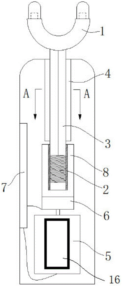
[0032] Such as figure 1 As shown, the driving part is the first sleeve 8 set on the outside of the driven part 2, the first sleeve 8 is provided with an internal thread, and the driven part 2 is provided with an external thread matching the internal thread, the first set The cylinder 8 is threadedly connected with the driven part 2 to form a screw mechanism, and the first sleeve 8 rotates in both positive and negative directions periodically and alternately to realize the periodic reciprocating movement of the connecting rod.

Embodiment 2

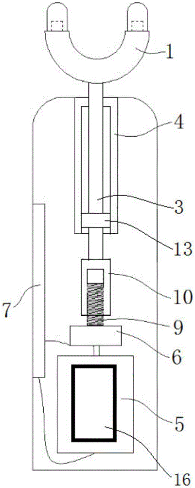
[0034] Such as figure 2 As shown, the driving part is a screw rod 9, the driven part 2 is a second sleeve 10, and the second sleeve 10 is provided with an internally threaded hole matched with the screw rod 9, and the screw rod 9 is threadedly connected to the second sleeve 10 to form a wire In the lever mechanism, the driving part rotates periodically in both forward and reverse directions to realize the periodic reciprocating movement of the connecting rod.

[0035] The cooperation between the positioning part 3 and the positioning sleeve 4 will be specifically described below through three embodiments.

Embodiment 3

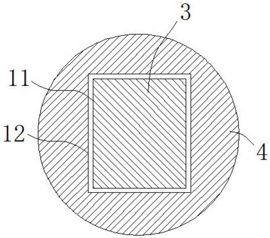
[0037] Such as image 3As shown, the positioning part 3 is a rod-shaped structure, and at least one first positioning surface 11 is provided on its side, and the second positioning surface 12 matching with the positioning surface is provided in the positioning sleeve 4. The cross-sectional shape of the positioning part 3 can be triangular , quadrangle, pentagon, hexagon and other polygons, if the first positioning surface 11 is an arc surface, the cross-sectional shape of the positioning portion 3 is oval, preferably a quadrangle in the above-mentioned embodiments, which is convenient for processing, simple in structure, and easy to manufacture. low cost.


PUM


Abstract

The invention relates to a noninvasive muscle bone joint detection corrector which comprises a massage contact, a connecting rod, a vibration generator and a numerical control system, wherein the vibration generator is arranged in a body; one end of the massage contact is fixedly connected with the connecting rod; the rod body of the connecting rod, positioned in the body, is divided into a driven part and a positioning part; the driven part is in fit connection with the vibration generator capable of enabling the connecting rod to reciprocate; the positioning part is in fit connection with a positioning sleeve capable of preventing the connecting rod from rotating axially; and the positioning sleeve is fixed in the body. The noninvasive muscle bone joint detection corrector provided by the invention consists of the massage contact, the connecting rod, the vibration generator, a force sensor and the numerical control system; the massage force is detected through the force sensor, and the vibration frequency of the vibration generator is controlled by the numerical control system; and the noninvasive muscle bone joint detection corrector is applicable to the massage force on the muscle bone joints at different body parts, realizes contact type vibration correction and stimulates the muscles and nerves around the joints to make the hardened muscles and nerves move and the deformed and displaced joints reset so as to achieve an aim of correction.

Description

technical field [0001] The invention relates to a hoisting connecting piece, in particular to a non-invasive musculoskeletal joint detection and correction instrument which acts on muscles and nerves around human musculoskeletal joints through vibration or resonance. Background technique [0002] In the field of life health and medical treatment, the main physiological functions of the musculoskeletal joint system include not only constituting the structure of the human body, but also protecting various organs in the body, performing various actions with the muscles and nervous system, and regulating the balance of ions in the body to maintain it. within the normal physiological range. Medical research results show that 80% of chronic diseases in the human body are mostly caused by deformation of muscles, bones and joints. The human body is affected by factors such as its own weight, aging and other factors such as external gravity, pressure, and occupational habitual postu...

Claims


Application Information

Patent Timeline
IPC IPC(8): A61F5/01A61H23/02
CPCA61F5/01A61H23/02A61H2201/1207A61H2201/14A61H2201/50A61H2201/5061
Inventor 彭康明郭红梅
Owner 彭康明
Why Eureka
Try Eureka