Emulsion and powder microsphere injection device and method

A technology of injection device and microspheres, which is used in earth-moving drilling, production of fluids, wellbore/well components, etc., can solve the problems of easy agglomeration, difficult dispersion, and difficulty of powder microspheres, and achieves a high degree of automation and control process. simple effect

Pending Publication Date: 2018-07-06
PETROCHINA CO LTD
0 Cites 0 Cited by

AI-Extracted Technical Summary

Problems solved by technology

However, due to the presence of dispersants and additives in emulsion microspheres, not only the cost of medicines has doubled, but also the volume, weight and packaging of medicines have also increased significantly, making the cost of medicines higher ...

Method used

[0033] As shown in Figures 1 to 3, the liquid storage and distribution unit includes a liquid storage tank. The liquid storage tank has a three-layer structure, which is an inner tank 1, an insulating layer 12 and an outer shell 13 from the inside to the outside. On the outer wall of the inner tank 1, heating cables 14 are evenly wound and distributed, and the heating cables 14 are connected to the control cabinet 9 through electric wires. The inner wall of the inner tan...

Abstract

The invention provides an emulsion and powder microsphere injection device and method. A liquid storage tank comprises an inner tank, a heat insulating layer and a shell, a heat tracing band is evenlywound around the outer wall of the inner tank, and the heat insulating layer is arranged between the inner tank and the shell; the inner wall of the inner tank is provided with a spoiler, and the inner tank is internally provided with a dispersing disc connected with a transmission shaft, and the transmission shaft is driven by a motor on the top of the liquid storage tank; a liquid outlet tube at the bottom of the liquid storage tank is provided with a low-pressure gate, the inlet end of a drug feeding pump is connected with the liquid outlet tube at the bottom of the liquid storage tank, and the inlet end of the drug feeding pump is provided with an input check valve; the outlet end of the drug feeding pump is connected with an output pipe which is connected to a water injection and distribution room or a water injection well opening; and an output check valve is arranged on the outlet end of the drug feeding pump, and the output tube is sequentially connected with a safety valve, apressure transmitter and a high-pressure gate; and signal lines of wires of the heat tracing band and the pressure transmitter are connected with a control cabinet which is connected with a switch ofthe drug feeding pump. The device can improve dissolution and dispersion of drugs.

Application Domain

Fluid removal

Technology Topic

EmulsionLiquid storage tank +11

Image

  • Emulsion and powder microsphere injection device and method
  • Emulsion and powder microsphere injection device and method
  • Emulsion and powder microsphere injection device and method

Examples

  • Experimental program(1)

Example Embodiment

[0031] The following describes the present invention in detail with reference to the drawings and specific embodiments:
[0032] Such as Figure 1 to Figure 4 As shown, the present invention is mainly composed of an injection unit and a liquid storage and distribution unit.
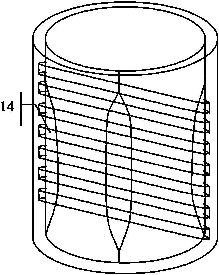
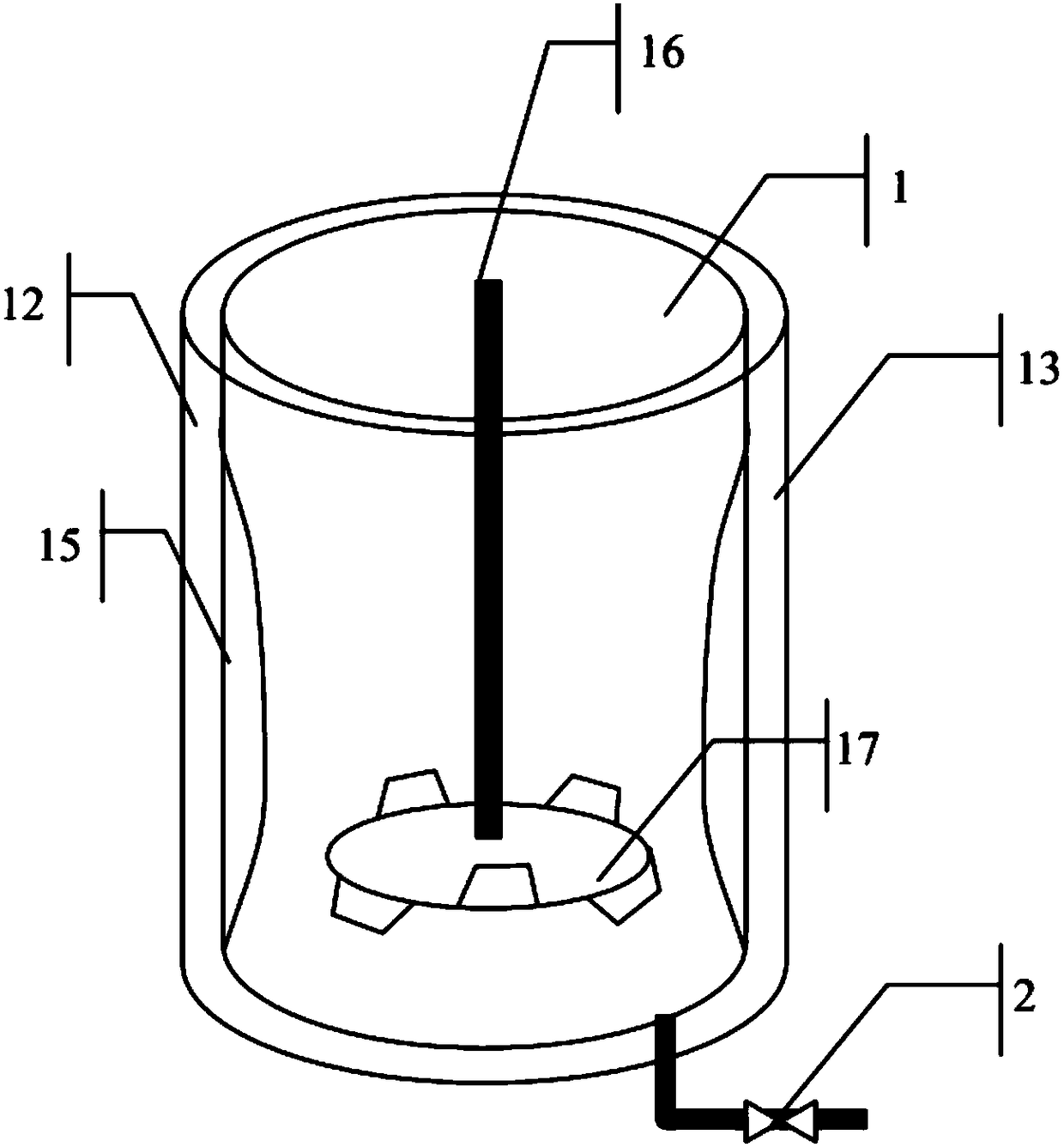
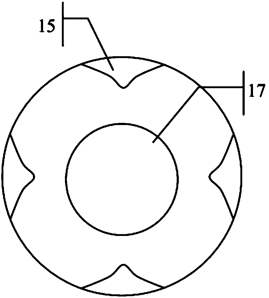
[0033] Such as Figure 1 to Figure 3 As shown, the liquid storage and distribution unit includes a liquid storage tank. The liquid storage tank has a three-layer structure, from the inside to the outside are the inner tank 1, the insulation layer 12 and the outer shell 13, respectively. A heating cable 14 is evenly wound on the outer wall of the inner tank 1, and the heating cable 14 is connected to the control cabinet 9 through wires. The inner wall of the inner tank 1 has 4 spoilers 15 which are uniformly distributed at 90°, which can increase the turbulence of the liquid in the tank and improve the dispersion effect. The inner tank 1 is provided with a dispersing disc 17 connected to the transmission shaft 16. The dispersing disc 17 is driven by a top motor to rotate. The dispersing disc 17 is provided with staggered trapezoidal blades with an angle of 45° from the upper and lower sides.
[0034] Such as Figure 4 As shown, the injection unit includes a control cabinet 9 and a dosing pump 4; the bottom of the liquid storage tank is connected to the low-pressure gate 2 through a pipeline, and then connected to the input check valve 3 by the pipeline, and the input check valve 3 is connected to the dosing pump 4 At the inlet end, the outlet end of the dosing pump 4 is connected to the output check valve 5 by a pipe, and then connected to the safety valve 6 by the pipe, and then connected to the pressure transmitter 8 by the pipe, and then connected to the high pressure gate 10 and finally by the output pipe 11. Connect to the water injection distribution room or water injection well head.
[0035] The control cabinet 9 is equipped with an automatic switch for controlling the heating cable 14, and the inner tank 1 is equipped with a temperature acquisition device (such as an electronic thermometer). The temperature acquisition device is connected with the automatic control switch. The automatic control switch is used to set the temperature threshold and automatically Turn on or off the control heating cable 14.
[0036] Among them, the relief valve vent 7 is connected to the sewage ditch through a pipeline; the signal line of the pressure transmitter 8 is connected to the control cabinet 9 and then to the switch of the dosing pump 4.
[0037] When the present invention is actually assembled, the specific connection sequence and working process are as follows:
[0038] 1. Pass the liquid storage tank The galvanized pipe is connected to the low pressure gate 2, and then by The galvanized pipe is connected to the input check valve 3, and then connected to the inlet end of the dosing pump 4, and the outlet end of the dosing pump 4 is used The high-pressure steel pipe is connected to the output check valve 5, and then by The high-pressure steel pipe is connected to the safety valve 6, and then The high-pressure steel pipe is connected to the pressure transmitter 8, and then connected to the high-pressure gate 10, and finally connected to the water injection distribution room or the water injection well head by the output pipe 11.
[0039] 2. Use safety valve vent 7 The galvanized pipe is connected to the sewage ditch; the signal line of the pressure transmitter 8 is connected to the control cabinet 9 and then to the switch of the dosing pump 4.
[0040] 3. When working, if it is emulsion type microspheres, pour the medicine into the storage tank directly through the low-pressure gate 2 and the input check valve 3 into the inlet end of the dosing pump 4, and flow through the dosing pump 4 after being pressurized After outputting the check valve 5, the safety valve 6, the pressure transmitter 8 and the high pressure gate 10, it enters the water injection distribution room or the water injection wellhead.
[0041] If it is powder type microspheres, first add clear water of the required concentration to the liquid storage tank 1, open the dispersing disc 17, and then slowly add the powder type microspheres to the liquid storage tank 1, and stir for about 10-20 minutes. Can be completely dispersed.
[0042] 4. Open the low pressure gate 2, (if used in winter, set the temperature to 50℃ through the automatic control switch. Since the temperature of the medicine in the tank is lower than 50℃, the heating cable 14 will start to heat. When the temperature is 51℃, it will automatically disconnect Supply power to the heating cable 14 and stop heating. When the temperature in the tank is lower than the preset temperature by 10°C, that is, 40°C, the automatic switch restarts to supply power to the heating cable 14 to restore the heating state), and the liquid phase medicine is discharged from the liquid storage tank 1. The medium enters the inlet end of the dosing pump 4 through the low pressure gate 2 and the input check valve 3, and flows through the output check valve 5, the safety valve 6, the pressure transmitter 8 and the high pressure gate 10 after being pressurized by the dosing pump 4 Enter the water injection distribution room or water injection well.
[0043] 5. When the pressure is too high, the pressure transmitter 8 sends the data back to the control cabinet 9 and then automatically closes the dosing pump 4; if the starting pressure of the safety valve 6 is reached, the safety valve 6 opens, and the pressure is released through the safety valve vent 7 , Waiting for the staff to repair.
[0044] The above are only preferred embodiments of the present invention and not limited to the scope of implementation of the present invention. All equivalent changes and modifications made in accordance with the content of the patent scope of the present invention shall fall within the technical scope of the present invention.

PUM

no PUM

Description & Claims & Application Information

We can also present the details of the Description, Claims and Application information to help users get a comprehensive understanding of the technical details of the patent, such as background art, summary of invention, brief description of drawings, description of embodiments, and other original content. On the other hand, users can also determine the specific scope of protection of the technology through the list of claims; as well as understand the changes in the life cycle of the technology with the presentation of the patent timeline. Login to view more.

Similar technology patents

Terminal permission control method and device

InactiveCN107172044ASimple control processsave resources
Owner:SHENZHEN IPANEL TECH LTD

Control method of motor controller integrated assembly for electric vehicle, and electric vehicle

PendingCN113676109ASimple control processSimple and reliable control process
Owner:江苏聚磁电驱动科技有限公司

Capacitor voltage balance control method and system for five-level Buck/Boost converter

ActiveCN112994450ASimple control processeffective realization
Owner:HUAZHONG UNIV OF SCI & TECH

Control method and system of cascaded H-bridge multi-level converter

ActiveCN111245200ASimple control processSimplify the modulation process
Owner:CHINA EPRI SCIENCE & TECHNOLOGY CO LTD +1

Coring drill mud pump control method for railway engineering exploration

InactiveCN110985366ASimple structureSimple control process
Owner:四川诺克钻探机械有限公司

Classification and recommendation of technical efficacy words

  • Simple control process
  • high degree of automation

Method, device and system for controlling multiple display devices

ActiveCN104080012AImprove control efficiencySimple control process
Owner:GUANGDONG OPPO MOBILE TELECOMM CORP LTD

Method and device for controlling real-time dynamic temperatures of machine room and base station

InactiveCN102466297Aeffective control processSimple control process
Owner:秦金红

Optical apparatus having device for removing foreign substance

ActiveUS20080297646A1simple control processprevent generation of noise
Owner:CANON KK

Control method and device of stereo sound system

ActiveCN105959878ASimple control processImprove operational efficiency
Owner:GUANGDONG OPPO MOBILE TELECOMM CORP LTD

High-fineness urban three-dimensional modeling method

Owner:星际空间(天津)科技发展有限公司

Bolt machining all-in-one machine

Owner:ANHUI LIUFANG ZHONGLIAN MECHANICAL SHARE
Why Eureka
Try Eureka