Box frame splicing structure

A box frame and frame strip technology, applied in the field of freezer box frame splicing structure, can solve the problems of yellowing of frame strips, dirty appearance, poor adhesion, etc., to improve adhesion, avoid aesthetics, and facilitate uniform distribution. Effect

Pending Publication Date: 2018-07-06
GUANGDONG HOMA REFRIGERATOR CO LTD
0 Cites 0 Cited by

AI-Extracted Technical Summary

Problems solved by technology

As for the connection between two frame strips, the traditional solution can choose screw connection, hot melt glue connection, glue coating, etc., bu...

Method used

The present invention can increase the glue storage capacity on the splicing area by setting the first glue flow channel 5 and the second glue flow channel 6 at the insert 3, improve the connection strength of the frame bar splicing position, and ensure the firmness of the box frame , and the connection between the first glue flow channel 5 and the second glue flow channel 6 is conducive to the uniform distribution of glue,...

Abstract

The invention relates to a box frame splicing structure. A box frame comprises a plurality of first frame bars and a plurality of second frame bars, wherein the two ends of each first frame bar are equipped with insertion sheets; the two ends of each second frame bar are equipped with insertion slots which are matched and spliced with the insertion sheets; and a plurality of first glue runners which extend in a splicing direction and are uniformly arranged in a spaced mode in a direction perpendicular to the splicing direction, and at least one second glue runner which extends in a direction perpendicular to the splicing direction and communicates with each first glue runner are arranged on each insertion sheet. The box frame splicing structure can be adopted, so that connecting strength can be improved, and glue is prevented from overflowing.

Application Domain

Domestic cooling apparatusLighting and heating apparatus

Technology Topic

EngineeringMechanical engineering +1

Image

  • Box frame splicing structure
  • Box frame splicing structure
  • Box frame splicing structure

Examples

  • Experimental program(1)

Example Embodiment

[0013] The technical solutions in the embodiments of the present invention will be clearly and completely described below in conjunction with the accompanying drawings in the embodiments of the present invention. Obviously, the described embodiments are only a part of the embodiments of the present invention, rather than all the embodiments. Based on the embodiments of the present invention, all other embodiments obtained by those of ordinary skill in the art without creative work shall fall within the protection scope of the present invention.
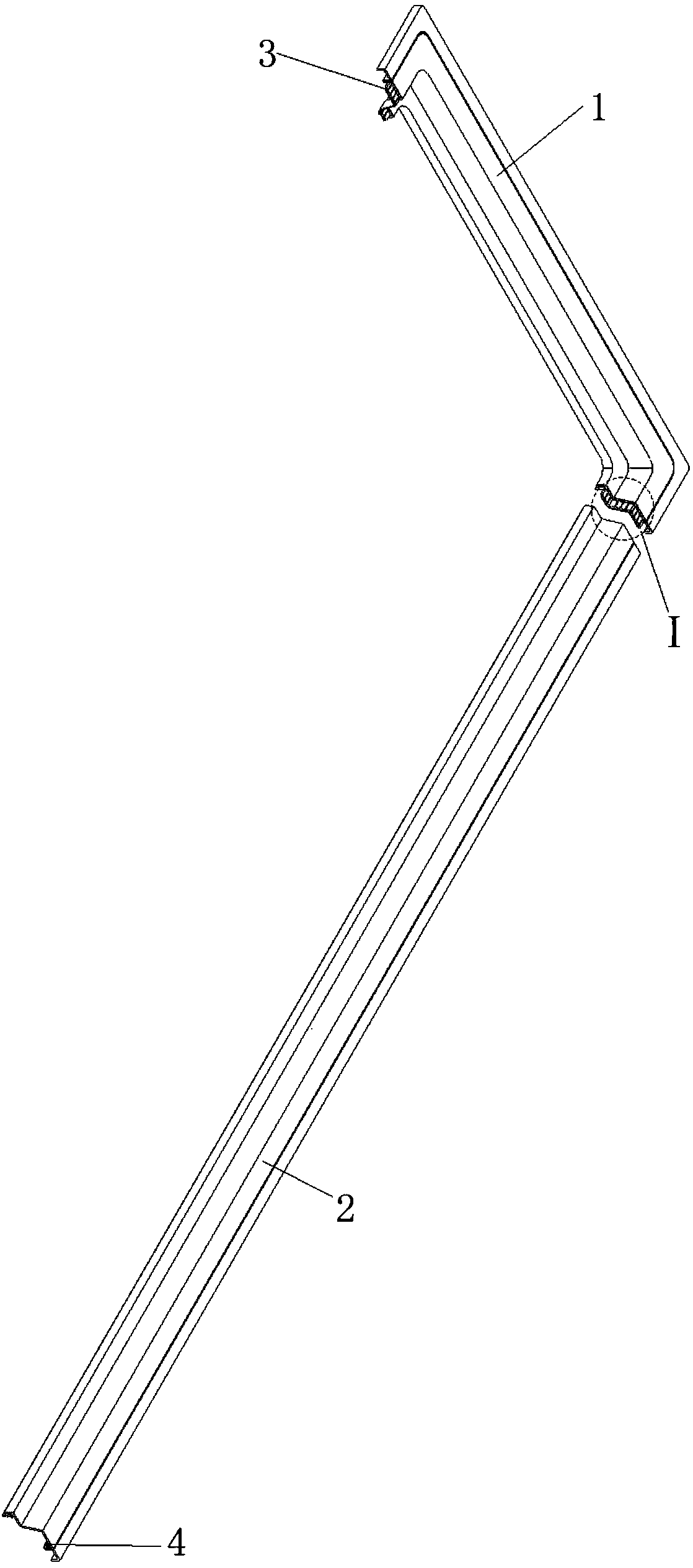
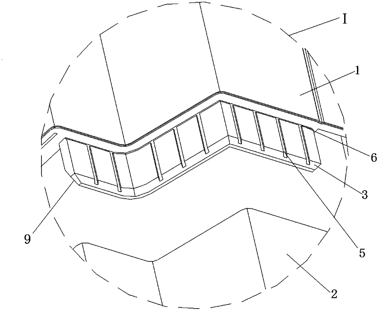
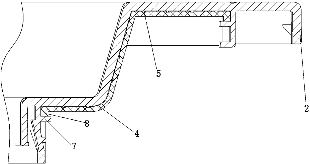
[0014] Such as Figure 1 to Figure 3 As shown, a preferred embodiment of the present invention is a box frame splicing structure. The box frame includes a plurality of first frame bars 1 and a plurality of second frame bars 2, and both ends of the first frame bars 1 are provided with inserts. Sheet 3, both ends of the second frame strip 2 are provided with slots 4 for mating insertion with the insert sheet 3, and the insert sheet 3 is provided with a plurality of slots extending in the inserting direction and perpendicular to the insert The first glue flow channels 5 are evenly spaced in the connecting direction, and at least one second glue flow channel 6 extending perpendicular to the plugging direction and communicating with each of the first glue flow channels 5.
[0015] In the present invention, the first glue flow channel 5 and the second glue flow channel 6 are arranged on the insert 3, which can increase the glue storage capacity in the splicing area, improve the connection strength of the splicing part of the frame strip, and ensure the firmness of the box frame. The first glue flow channel 5 and the second glue flow channel 6 are connected, which is conducive to the uniform distribution of glue, reduces the phenomenon of glue overflow, can save the steps of handling overflow glue, and avoids affecting the aesthetics of the product.
[0016] More preferably, the inner walls of both sides of the slot 4 are provided with guiding slide grooves 7, and both sides of the insert piece 3 are provided with guiding sliders 8 that are connected to the guiding slide groove 7. Such a structure can improve the stability of the insert 3 and facilitate assembly.
[0017] More preferably, the front end of the insert 3 is provided with a guiding inclined surface 9. Through the provision of the guide slope 9, the insert 3 can be inserted into the slot 4 more easily.
[0018] The above-disclosed are only preferred embodiments of the present invention. Of course, the scope of rights of the present invention cannot be limited by this. Therefore, equivalent changes made in accordance with the scope of the patent application of the present invention still fall within the scope of the present invention.

PUM

no PUM

Description & Claims & Application Information

We can also present the details of the Description, Claims and Application information to help users get a comprehensive understanding of the technical details of the patent, such as background art, summary of invention, brief description of drawings, description of embodiments, and other original content. On the other hand, users can also determine the specific scope of protection of the technology through the list of claims; as well as understand the changes in the life cycle of the technology with the presentation of the patent timeline. Login to view more.

Similar technology patents

Composite body

InactiveCN102834210AImprove joint strengthImprove adhesion
Owner:TUNGALOY CORP

Enhancing adhesion of cap layer films

InactiveUS20140094038A1improve adhesionenhance surface modification
Owner:NOVELLUS SYSTEMS

Acid-proof wear-proof anticorrosive paint and its preparing method

InactiveCN1986711AImprove anti-corrosion performanceImprove adhesion
Owner:江苏溧竹环境工程有限公司

Environment-friendly antimicrobial odorless latex paint

InactiveCN102964956AImprove adhesionhigh surface finish
Owner:上海滋普环保科技有限公司

Classification and recommendation of technical efficacy words

Why Eureka
Try Eureka