Full-bridge LLC resonant conversion circuit and wide-range output control method thereof

A technology of resonant conversion and conversion circuit, applied in the direction of converting DC power input to DC power output, control/regulation system, output power conversion device, etc., can solve the problem that the control method is difficult to satisfy high efficiency and wide output voltage at the same time , to achieve the effect of small output voltage ripple, high efficiency and wide output voltage range

Inactive Publication Date: 2018-07-06
ZHEJIANG UNIV
View PDF4 Cites 20 Cited by
  • Summary
  • Abstract
  • Description
  • Claims
  • Application Information

AI Technical Summary

Problems solved by technology

However, the LLC resonant conversion circuit belongs to the variable frequency voltage regulation converter, and the traditional control method is difficult to meet the requirements of high efficiency and wide output voltage at the same time.

Method used


Image

  • Full-bridge LLC resonant conversion circuit and wide-range output control method thereof
  • Full-bridge LLC resonant conversion circuit and wide-range output control method thereof
  • Full-bridge LLC resonant conversion circuit and wide-range output control method thereof

Examples


Embodiment 1

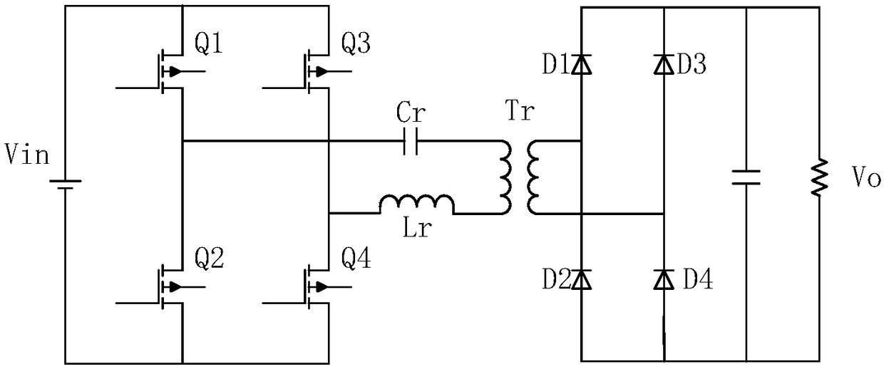
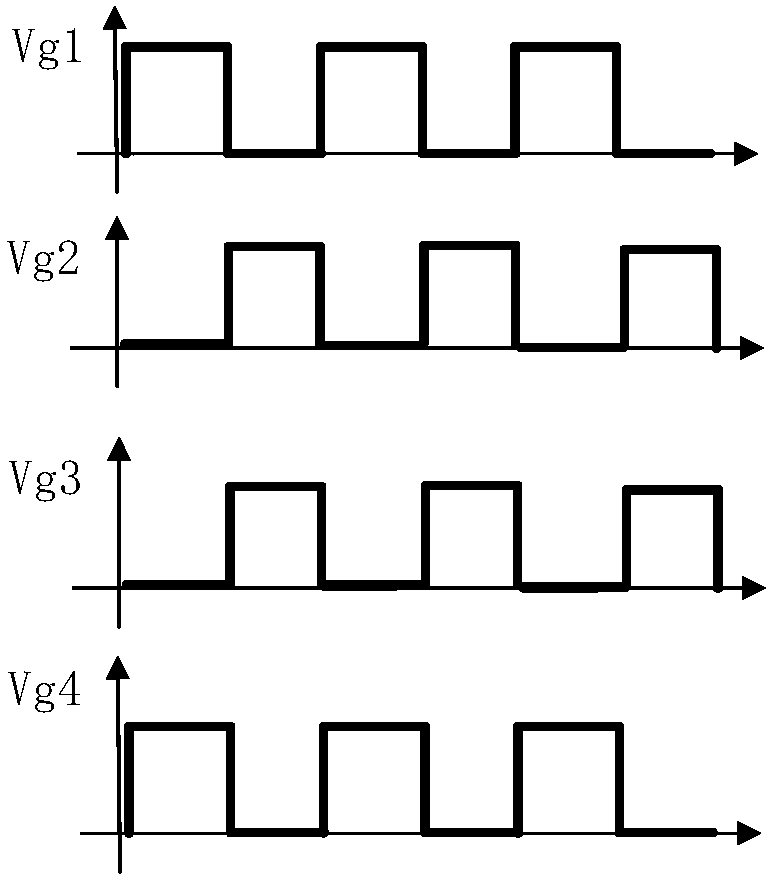
[0024] Such as figure 1 Shown is a full-bridge LLC resonant conversion circuit suitable for the method of the present invention, and can also be applied to a full-wave rectification type LLC resonant conversion circuit. figure 1 In the circuit shown, four switch tubes Q1, Q2, Q3, Q4, four full-bridge rectifier diodes D1, D2, D3, D4, and resonant capacitor Cr, resonant inductor Lr, and resonant transformer Tr form a full-bridge LLC resonant conversion circuit . The gate signals of the four switch tubes Q1, Q2, Q3, and Q4 are Vg1, Vg2, Vg3, and Vg4, respectively.

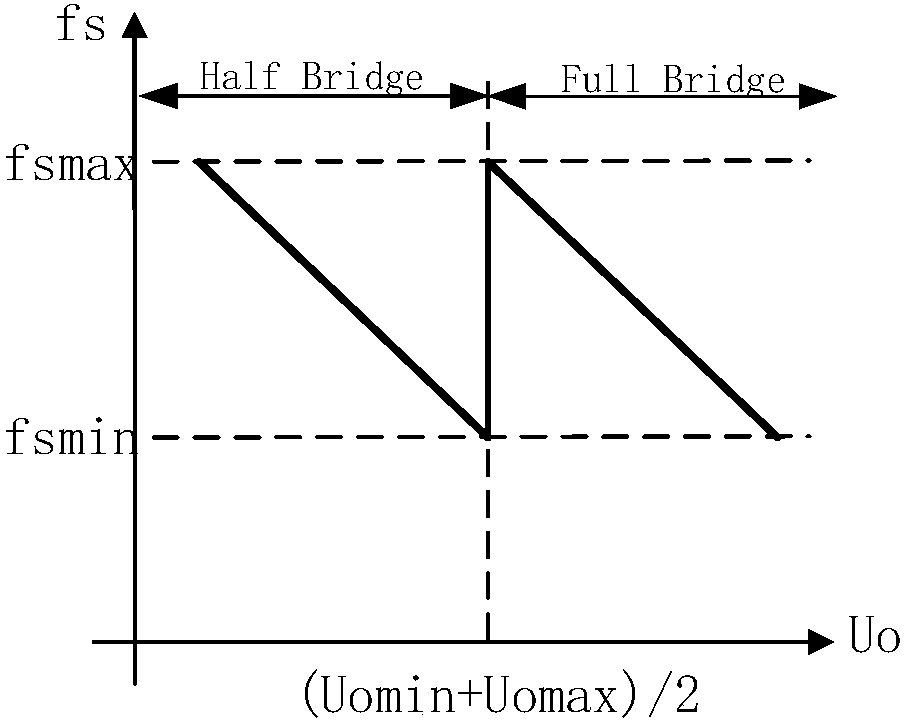
[0025] Such as figure 2 As shown, the wide-range output control method of the full-bridge LLC resonant conversion circuit provided by the present invention is as follows:

[0026] When the output voltage Uo is greater than (Uomax+Uomin) / 2, make the full-bridge LLC resonant conversion circuit work in the full-bridge working mode, and adjust the voltage by frequency conversion;

[0027] When the output voltage Uo i...

Embodiment 2

[0034] Such as figure 1 Shown is a full-bridge LLC resonant conversion circuit suitable for the method of the present invention, and can also be applied to a full-wave rectification type LLC resonant conversion circuit. figure 1 In the circuit shown, four switch tubes Q1, Q2, Q3, Q4, four full-bridge rectifier diodes D1, D2, D3, D4, and resonant capacitor Cr, resonant inductor Lr, and resonant transformer Tr form a full-bridge LLC resonant conversion circuit . The gate signals of the four switch tubes Q1, Q2, Q3, and Q4 are Vg1, Vg2, Vg3, and Vg4, respectively.

[0035] Such as Figure 5 As shown, the wide-range output control method of the full-bridge LLC resonant conversion circuit with hysteresis switching provided by the present invention is as follows:

[0036] When the output voltage Uo is greater than (Uomax+Uomin) / 2+ε, make the full-bridge LLC resonant conversion circuit work in the full-bridge working mode, and adjust the voltage by frequency conversion;

[0037] ...


PUM


Abstract

The invention provides a full-bridge LLC resonant conversion circuit. The full-bridge LLC resonant conversion circuit comprises a conversion circuit and a rectification circuit, wherein the conversioncircuit comprises four switch tubes Q1, Q2, Q3 and Q4, the conversion circuit is partially provided with a resonant capacitor Cr and a resonant inductor Lr which are connected in series, one end of the resonant inductor Cr is connected with a bridge arm, the resonant inductor Lr is connected with the other one bridge arm. The invention provides a wide-range output control method of the full-bridge LLC resonant conversion circuit. According to the wide-range output control method, the full-bridge LLC resonant conversion circuit works in a full-bridge working mode when an output voltage U0 is larger than (U<0max>+U<0min>) / 2; and the switching between the full-bridge working mode and a half-bridge working mode is performed when the full-bridge LLC resonant conversion circuit works in the half-bridge working mode and the output voltage is equal to (U<0max>+U<0min>) / 2. By the full-bridge LLC resonant conversion circuit, a wider output voltage range can be provided, and a better output characteristic index such as higher efficiency and smaller output voltage ripple can be obtained.

Description

technical field [0001] The invention relates to a full-bridge LLC resonant conversion circuit, and at the same time relates to a circuit output control method, in particular to a wide-range output control method of the full-bridge LLC resonant conversion circuit. Background technique [0002] At present, there are roughly two battery terminal voltage ranges for electric vehicles, 200V-500V and 300V-750V. If a charger can charge batteries in two voltage ranges, it can greatly reduce the construction cost of charging piles and improve economic benefits. [0003] The LLC resonant conversion circuit is favored by people in the industry because of its advantages of high efficiency and higher power density. However, the LLC resonant conversion circuit is a frequency-variable voltage-regulating converter, and the traditional control method is difficult to meet the requirements of high efficiency and wide output voltage at the same time. Contents of the invention [0004] The fi...

Claims


Application Information

Patent Timeline
Patent Type & Authority Applications(China)
IPC IPC(8): H02M3/335
CPCH02M3/3353H02M3/33592Y02B70/10
Inventor 温剑威盛况张军明
Owner ZHEJIANG UNIV
Why Eureka
Try Eureka