
Centrifugal dust removal equipment

A kind of dust removal equipment and centrifugal technology, which is applied in the direction of centrifuges, smoke and dust removal, mining equipment, etc., can solve the problems of inability to concentrate, endanger the health of workers, and easily suffer from occupational diseases, so as to improve the quality of the working environment and make it more convenient. Move at any time, extensive use of the foreground effect

Inactive Publication Date: 2018-07-10
天津泰广网络科技有限公司
View PDF0 Cites 2 Cited by
  • Summary
  • Abstract
  • Description
  • Claims
  • Application Information

AI Technical Summary

Problems solved by technology

[0002] When mining in mines such as coal mines, metal mines and non-metallic mines or in tunnels, more dust and water mist are usually produced. The existence of such dust and water mist has certain hazards: 1. Operators who work in an environment with a lot of dust and water mist for a long time are prone to occupational diseases and endanger the health of the operators; 2. If there is too much dust and water mist, the visibility is low and it is easy to cause transportation safety accidents.
[0003] In the prior art, there are existing equipment for ventilation and dust removal in mines. The machine has a good dust removal effect, but the explosion-proof fan will generate relatively large noise during operation, which will be unfavorable to personnel working in mines or tunnels. The impact will make the staff unable to concentrate and lead to low work efficiency, and there are hidden dangers to personal safety.

Method used


Image

  • Centrifugal dust removal equipment
  • Centrifugal dust removal equipment
  • Centrifugal dust removal equipment

Examples


Embodiment Construction

[0016] The following will clearly and completely describe the technical solutions in the embodiments of the present invention with reference to the accompanying drawings in the embodiments of the present invention. Obviously, the described embodiments are only some, not all, embodiments of the present invention. Based on the embodiments of the present invention, all other embodiments obtained by persons of ordinary skill in the art without making creative efforts belong to the protection scope of the present invention.

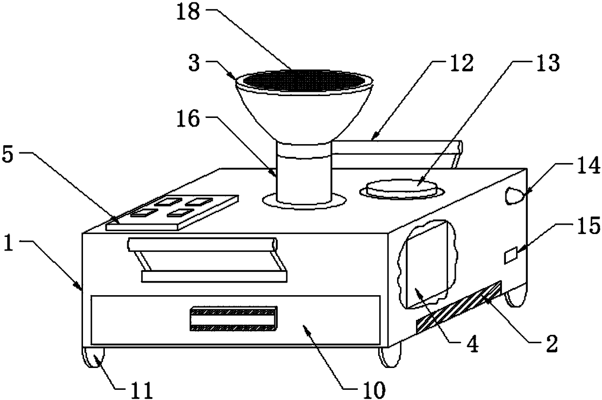
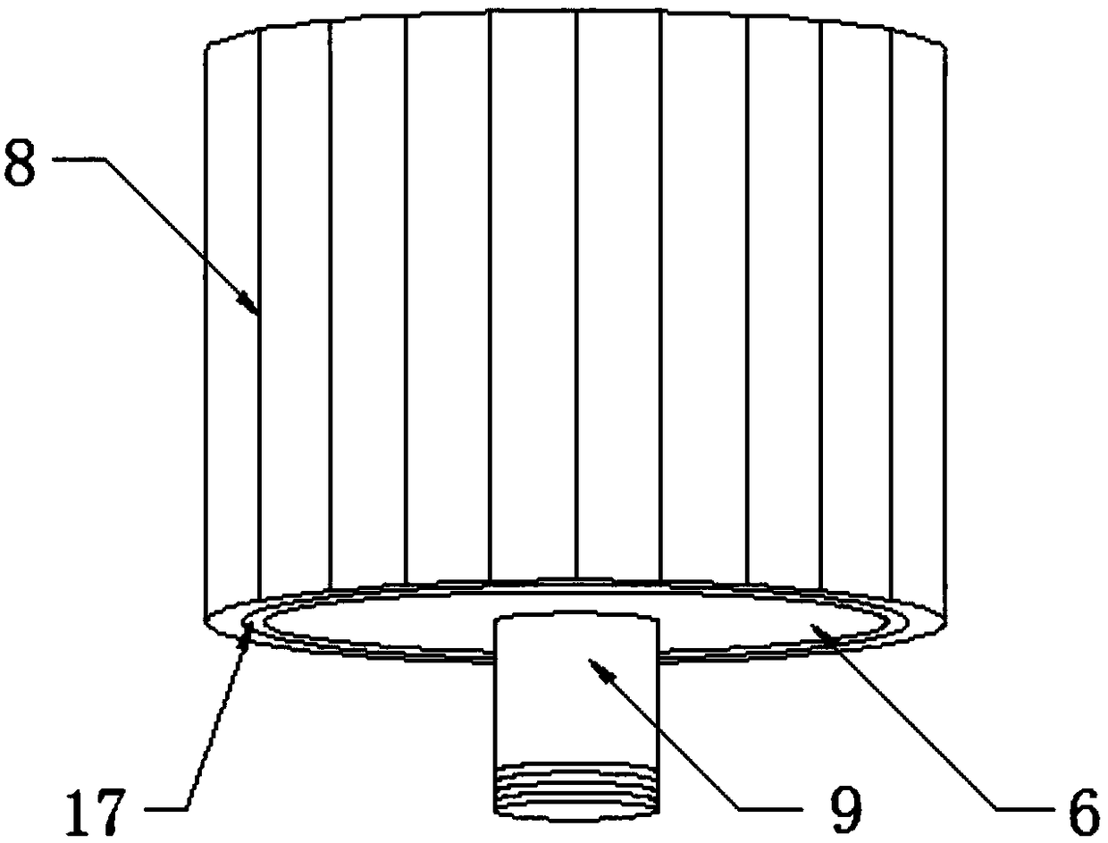
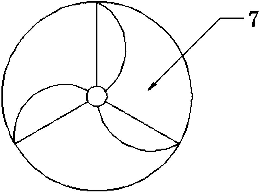
[0017] see Figure 1-3 , the present invention provides a technical solution: a centrifugal dust removal equipment, including a device body 1 made of stainless steel chamfering material, the device body 1 is composed of a rotating motor 2 and a centrifuge 6 arranged inside the device body 1 and arranged on the The dust suction port 3 on the top of the device body 1 is formed, the bottom end of the centrifuge 6 is provided with a rotating shaft 9, and the centr...


PUM


Abstract

The invention discloses centrifugal dust removal equipment which comprises a device body. The device body is made of stainless steel chamfer materials and comprises a rotary motor, a centrifugal machine and a dust suction opening, the rotary motor and the centrifugal machine are arranged inside the device body, the dust suction opening is formed in the top of the device body, a rotary shaft is arranged at the bottom of the centrifugal machine, and the centrifugal machine is movably connected with the rotary motor by the rotary shaft. The centrifugal dust removal equipment has the advantages that the centrifugal dust removal equipment is made of the stainless steel materials, a storage device is used as power, and accordingly the device body is light, is low in noise and can conveniently move at any time; resonance and noise can be prevented, and accordingly the safety of workers for underground operation and deep-well operation can be greatly enhanced; water mist and dust in air can besucked into the centrifugal machine by the dust suction opening and a turbine, adsorption filter paper which is quite easy to replace is arranged on the side surfaces of the centrifugal machine, accordingly, large quantities of moisture and the dust can be adsorbed, the quality of work environments for the downhole workers can be greatly enhanced, and the physical health of the workers can be effectively guaranteed.

Description

technical field [0001] The invention relates to the technical field of automobile equipment, in particular to centrifugal dust removal equipment. Background technique [0002] When mining in mines such as coal mines, metal mines and non-metallic mines or in tunnels, more dust and water mist are usually produced. The existence of such dust and water mist has certain hazards: 1. Operators who work in an environment with a lot of dust and water mist for a long time are prone to occupational diseases and endanger the health of the operators; 2. If there is too much dust and water mist, the visibility is low and it is easy to cause transportation safety accidents. [0003] In the prior art, there are existing equipment for ventilation and dust removal in mines. The machine has a good dust removal effect, but the explosion-proof fan will generate relatively large noise during operation, which will be unfavorable to personnel working in mines or tunnels. The impact will make the s...

Claims


Application Information

Patent Timeline
Patent Type & Authority Applications(China)
IPC IPC(8): B01D45/12B01D50/00B04B5/08B08B15/04E21F5/00E21F5/20
CPCB01D45/12E21F5/00E21F5/20B04B5/08B08B15/04B01D50/20
Inventor 田允劼
Owner 天津泰广网络科技有限公司
Learn More