Electronic controller clamping device

An electronic controller and clamping device technology, applied in program control devices, workpiece clamping devices, manufacturing tools, etc., can solve the problems of serious consumables, increase production costs, easy wear of test probes, etc. Improved stability and easy operation

Active Publication Date: 2018-07-10
LIANCHUANG AUTOMOBILE ELECTRONICS
View PDF9 Cites 1 Cited by
  • Summary
  • Abstract
  • Description
  • Claims
  • Application Information

AI Technical Summary

Problems solved by technology

However, in the process of program burning, because the position between the probe and the product cannot be related, and the accuracy error of the selected solder joint position itself and the influence of its own resistance value make the program burning process unstable, and it is easy to test the probe. Abrasion and consumables are serious. According to the research of an automotive electronics company, the burn-in method will lead to a product failure rate of about 0.8%. At the same time, the frequency of replacement of test probes is high, which seriously increases the production cost of the company.

Method used


Image

  • Electronic controller clamping device
  • Electronic controller clamping device
  • Electronic controller clamping device

Examples


Embodiment Construction

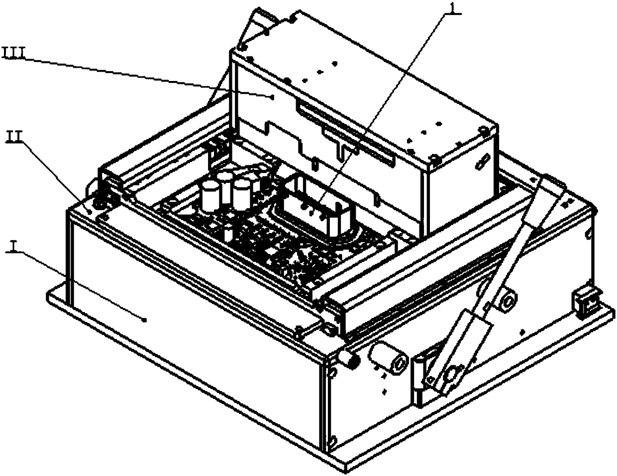
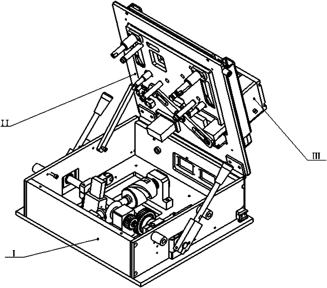
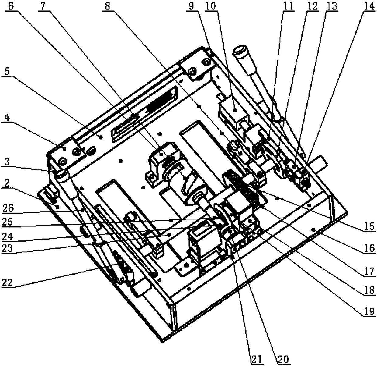
[0111] The electronic controller clamping device provided by the present invention includes: an upper case body, a lower case body, a handle rotation mechanism, a gear transmission mechanism, a plane cam mechanism, a space cam mechanism, a link mechanism, a probe floating mechanism and a product positioning assembly;

[0112] The handle rotation mechanism, the gear transmission mechanism and the space cam mechanism are arranged in the lower box body, and the plane cam mechanism, the link mechanism, the product positioning assembly and the probe floating mechanism are arranged in the upper box body;

[0113] The handle rotation mechanism is connected with the gear transmission mechanism and the plane cam mechanism, the gear transmission mechanism is connected with the space cam mechanism, the space cam mechanism is connected with the product positioning component, and the product positioning component is connected with the link mechanism and the probe floating mechanism.

[0114...


PUM


Abstract

The invention relates to an electronic controller clamping device of a vehicle. The device comprises an upper box, a lower box, a handle rotating mechanism, a gear transmission mechanism, a plane cammechanism, a space cam mechanism, a connecting rod mechanism, a probe floating mechanism, and a product positioning assembly. The handle rotating mechanism, the gear transmission mechanism, and the space cam mechanism are arranged on the lower box. The plane cam mechanism, the connecting rod mechanism, the product positioning assembly, and the probe floating mechanism are arranged on the upper box. Through external forces, a handle is pushed to realize triple transmission. In the first half of rotation of the handle, alignment of the product positioning assembly and the probe floating mechanism is realized. In the second half of rotation of the handle, the product positioning assembly is realized to vertically move upward, to complete butt joint of a product with a probe. At the moment, anelectromagnet locks a positioning plate to achieve a clamping maintaining state. The device is simple in operation and clever in mechanism, and is suitable for popularization and application.

Description

technical field [0001] The invention relates to the field of mechanical devices, in particular to a manual clamping device for an electronic controller to clamp a port under test. Background technique [0002] Among the automotive electronic controller products manufactured by auto parts companies on the market, one of the product structures is that the connector is arranged vertically with the PCBA, and the product is burned into the program through the connector. The program used by most companies on the market is burned into The device uses the PIN pin of the connector of the automotive electronic controller product to select the solder joint to perform the burn-in program. Although the process is relatively simple, the structure of the tooling is relatively simple, and the tooling only needs one action to achieve this function. However, in the process of program burn-in, because the position between the probe and the product cannot be correlated, and the accuracy error o...

Claims


Application Information

Patent Timeline
Patent Type & Authority Applications(China)
IPC IPC(8): B25B11/00G06F9/445
CPCB25B11/00G06F8/61
Inventor 汪文兵陈延平李小雷王永耀
Owner LIANCHUANG AUTOMOBILE ELECTRONICS
Why Eureka
Try Eureka