
Material conveying control method, device and system

A conveying control and conveying system technology, applied in the field of material conveying, can solve the problems of occupying the location of the main building, high energy consumption of the metering system, and uneconomical etc.

Inactive Publication Date: 2018-07-10
ZOOMLION HEAVY IND CO LTD
View PDF5 Cites 2 Cited by
  • Summary
  • Abstract
  • Description
  • Claims
  • Application Information

AI Technical Summary

Problems solved by technology

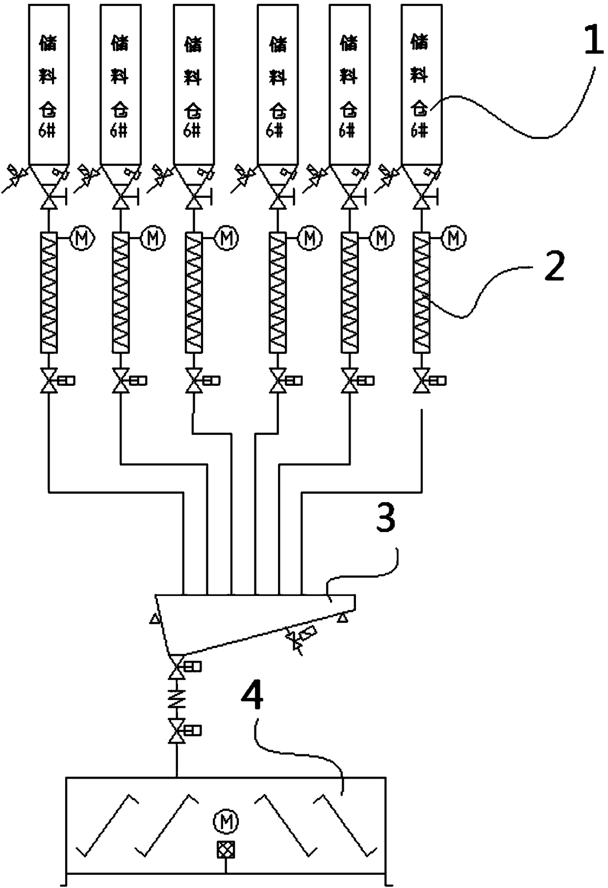
[0003] The inventors of this case found in the process of realizing the present invention that the current dry-mixed mortar additive metering system has high energy consumption, is uneconomical, and has a fixed layout. The metering scale bucket 3 needs to be placed above the mixer 4 and occupies the position of the main building.

Method used


Image

  • Material conveying control method, device and system
  • Material conveying control method, device and system
  • Material conveying control method, device and system

Examples


Embodiment Construction

[0034] The specific implementation manners of the embodiments of the present invention will be described in detail below in conjunction with the accompanying drawings. It should be understood that the specific implementation manners described here are only used to illustrate and explain the embodiments of the present invention, and are not intended to limit the embodiments of the present invention.

[0035] figure 2 It is a schematic structural diagram of a material conveying system provided by an embodiment of the present invention. Such as figure 2 As shown, an embodiment of the present invention provides a material conveying system, the material conveying system includes: a pneumatic conveying device for conveying the material to be conveyed in a pneumatic manner; and a material conveying control device, which can The weight, density, and conveying distance of the material determine an initial conveying pressure, and control the pneumatic conveying device to convey the ...


PUM


Abstract

The embodiment of the invention provides a material conveying control method, a material conveying control device and a material conveying system. The device comprises a receiving device for receivingweight, density and conveying distance of materials to be conveyed and a control device for determining an initial conveying pressure according to the weight, density and conveying distance of the materials to be conveyed, and controlling a pneumatic conveying device to convey the materials to be conveyed at the initial conveying pressure. Through the above technical scheme, by adopting the pneumatic conveying device, the position arrangement between a material conveying end and a receiving end can be more flexible, and the pneumatic conveying device can also adjust conveying speed of the materials by adjusting conveying pressure, so that the time of the material conveying can be flexibly adjusted to more flexibly meet production line requirements for production efficiency.

Description

technical field [0001] The present invention relates to the field of material conveying, in particular to a material conveying control method, a material conveying control device and a material conveying system. Background technique [0002] figure 1 It is a structural schematic diagram of an existing dry-mixed mortar flexible additive metering delivery system. Such as figure 1 As shown, the dry-mixed mortar additive metering system generally includes a storage bin 1 , a screw machine 2 , a weighing bucket 3 and a mixer 4 . There may be multiple storage bins 1, each of which can store a material (for example, cement, sand and gravel, etc.). According to the production requirements, the dry-mixed mortar additive metering system can firstly transport the material in a certain storage bin to the weighing hopper 3 through the screw machine 2, and put it into the mixer 4 after the predetermined amount is measured by the weighing hopper 3. After the materials to be mixed are p...

Claims


Application Information

Patent Timeline
IPC IPC(8): B28C7/06
CPCB28C7/062
Inventor 王子吉力胡扬安宁王志刚
Owner ZOOMLION HEAVY IND CO LTD
Learn More