Engine, fuel nozzle and collector ring

An oil collecting ring and oil circuit technology, which is applied to engine components, engine cooling, turbine/propulsion cooling, etc., can solve problems such as fuel deposition, coking, and poor fuel atomization, and achieve good cooling effect and coking. low probability effect

Active Publication Date: 2018-07-10
AECC COMML AIRCRAFT ENGINE CO LTD
View PDF6 Cites 10 Cited by
  • Summary
  • Abstract
  • Description
  • Claims
  • Application Information

AI Technical Summary

Problems solved by technology

However, the cooling method in the prior art still cannot completely solve the problem of excessive fuel temperature
Fuel deposits and coking are still very easy to occur near the oil collector ring
Therefore, oil collectors equipped with traditional cooling devices still often suffer from poor fuel atomization and unstable atomization quality

Method used


Image

  • Engine, fuel nozzle and collector ring
  • Engine, fuel nozzle and collector ring
  • Engine, fuel nozzle and collector ring

Examples


Embodiment Construction

[0028] Embodiments of the present invention will now be described in detail with reference to the accompanying drawings. Reference will now be made in detail to the preferred embodiments of the invention, examples of which are illustrated in the accompanying drawings. Wherever possible, the same numbers will be used throughout the drawings to refer to the same or like parts. In addition, although the terms used in the present invention are selected from well-known and commonly used terms, some terms mentioned in the description of the present invention may be selected by the applicant according to his or her judgment, and the detailed meanings thereof are set forth herein described in the relevant section of the description. Furthermore, it is required that the present invention be understood not only by the actual terms used, but also by the meaning implied by each term.

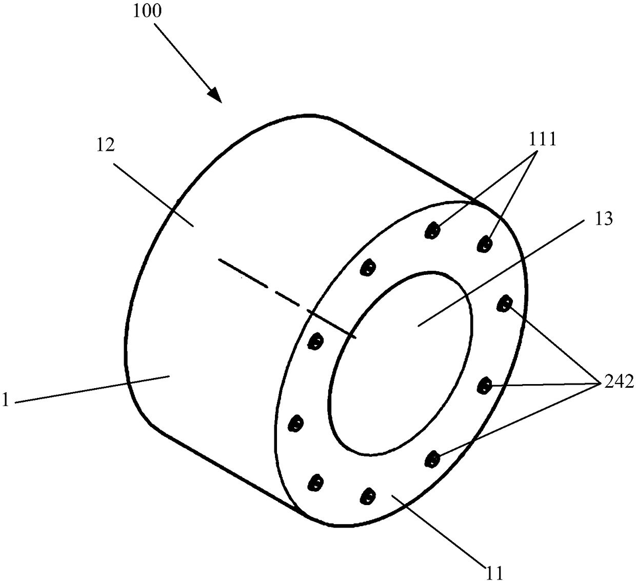
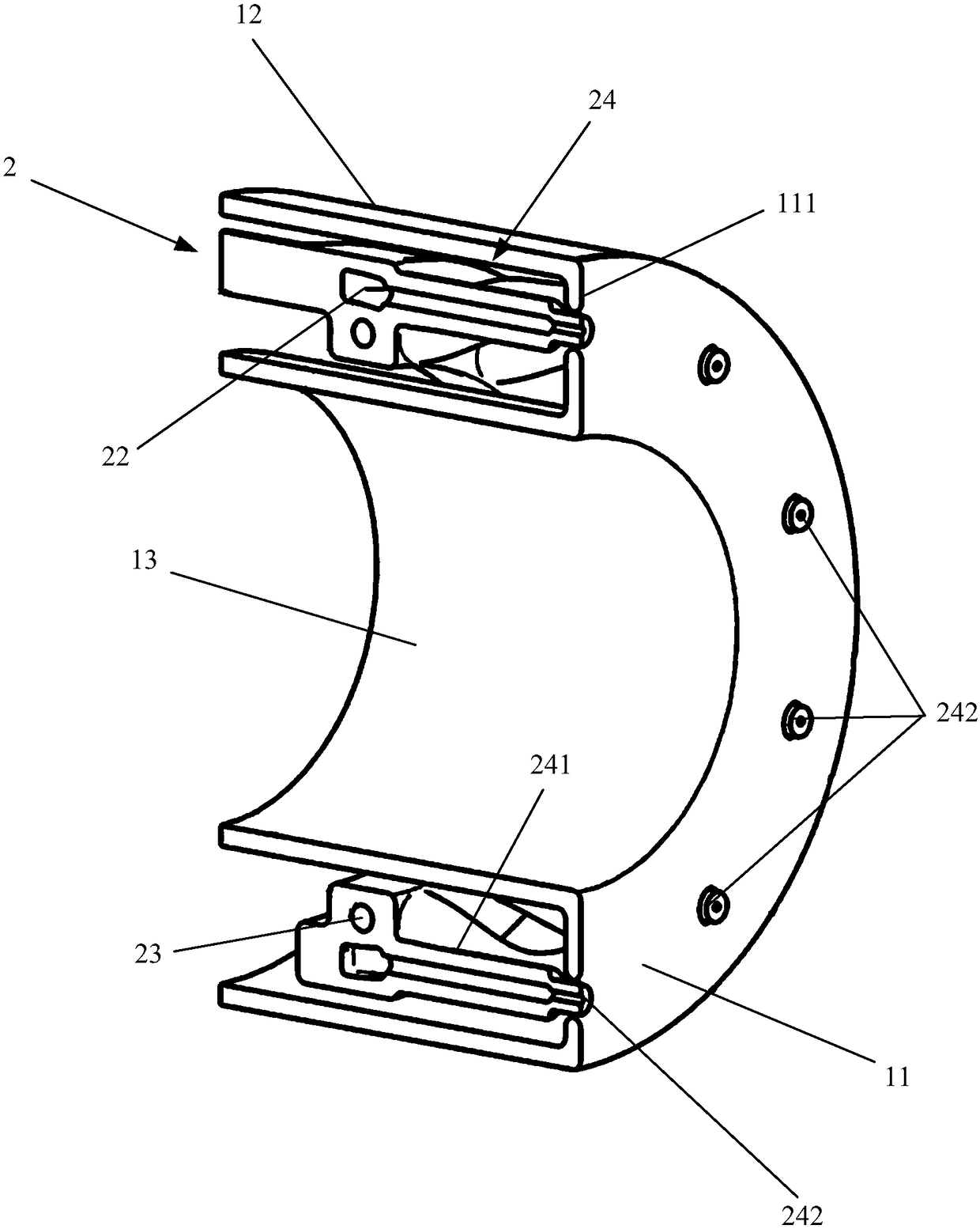
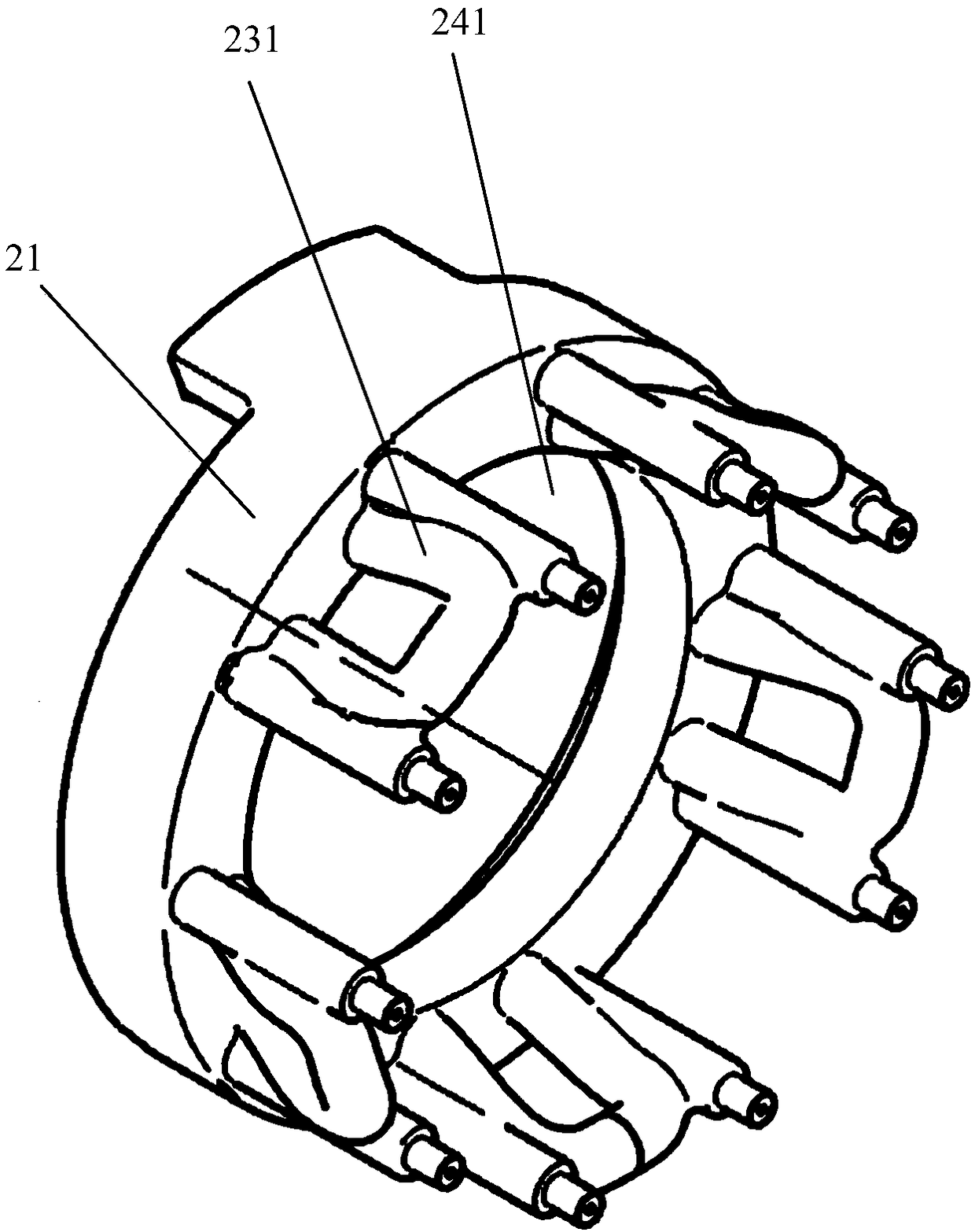
[0029] first reference figure 1 , 2 , 3a, 3b, and 3c to illustrate the structure of the oil collecto...


PUM


Abstract

The invention provides a collector ring, comprising a shell and a fuel circuit component. The shell has a circular bottom, an outer wall and an inner wall; the circular bottom has at least one spout hole. The fuel circuit component is arranged between the outer wall and the inner wall and includes a first fuel line, a second fuel line and at least one injector rod component. Each injector rod component includes a rod communicated with the first fuel line and extended to the circular bottom, and a spout positioned in the end of the rod and extended out of the corresponding spout hole. The second fuel line includes a second fuel line body and at least one bent portion extended to the circular bottom; at least part of each bent portion is abutted to the rod. Compared with existing fuel nozzles, the collector ring using the above technical scheme has the advantages of good cooling effect and low chances for fuel deposition and coking.

Description

technical field [0001] The invention relates to an engine, a fuel injection nozzle and an oil collection ring thereof, in particular to a fuel injection nozzle with a heat protection structure and an oil collection ring suitable for an aircraft. Background technique [0002] With the development of high-performance and high-pressure ratio aero-engines, the demand for using fuel as a coolant to cool the engine device is increasing rapidly, making the temperature of the fuel before entering the oil collector ring rise as high as 100-140°C. At the same time, as the engine pressure ratio continues to increase to improve cycle efficiency, the inlet air temperature of the combustion chamber is also further increased. The air temperature at the inlet of the combustion chamber of the first-stage engine with a thrust-to-weight ratio of 10 is above 800K, which makes the oil temperature in the oil collection ring and the wall temperature of the oil pipe continuously increase, resulting...

Claims


Application Information

Patent Timeline
Patent Type & Authority Applications(China)
IPC IPC(8): F02C7/16F02C7/22
Inventor 李德龙陈毓卿
Owner AECC COMML AIRCRAFT ENGINE CO LTD
Why Eureka
Try Eureka