Emergency plugging device for valve leakage opening

A leakage and valve technology, applied in the direction of pipes/pipe joints/fittings, mechanical equipment, pipe components, etc., can solve the problems of cumbersome operation, inconvenient valve maintenance, inconvenience, etc., and achieve simple equipment structure, convenient operation and simple operation Effect

Inactive Publication Date: 2018-07-10
GOTT HLDG GRP CO LTD
View PDF10 Cites 1 Cited by
  • Summary
  • Abstract
  • Description
  • Claims
  • Application Information

AI Technical Summary

Problems solved by technology

[0002] Leakage emergency plugging device is a pipeline emergency repair device. It is a device for emergency repair of water leakage at the socket at the joint of two pipes. The quick leak plugging device is made of cast iron and steel, and can be widely used in water supply and drainage and Water and air leakage accidents caused by trachoma, pores, transverse and longitudinal fractures of various liquid, gas and pressure pipes, saving labor, time and cost, suitable for various cast iron pipes, steel pipes, cement pipes, PVC pipes and PPR pipes Water leakage, air leakage, and maintenance; the existing blocking devices have certain disadvantages in use. First of all, when the pipeline leaks and the valve is damaged and repaired, the entire pipeline system cannot be used, which has brought great harm to production and life. Inconvenient, secondly, the existing emergency plugging device is not very convenient to install and disassemble, the operation is cumbersome, often can not timely plugging, also, the plugging effect is not very good, only the plugging structure is single, the gas inside the pipeline or The liquid is easy to leak, which brings inconvenience to the maintenance of the valve. For this reason, we propose an emergency plugging device for valve leakage

Method used


Image

  • Emergency plugging device for valve leakage opening
  • Emergency plugging device for valve leakage opening
  • Emergency plugging device for valve leakage opening

Examples


Embodiment 1

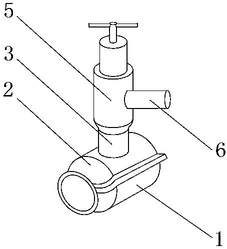
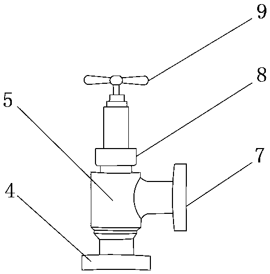
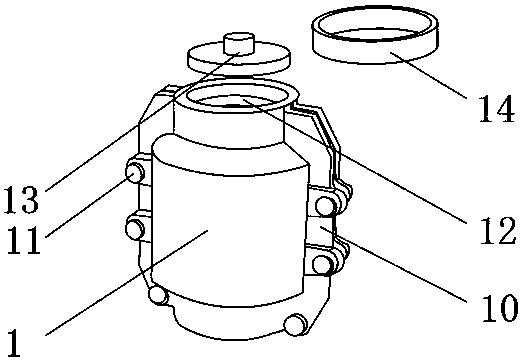
[0020] Such as Figure 1-4 As shown, an emergency plugging device for a valve leak includes a lower casing 1, and an upper casing 2 is movably installed on the outer surface of the upper end of the lower casing 1, and the emergency blocking device can be quickly installed. The operation is simple and easy to use, and can be timely Plugging, the outer surface of the upper end of the upper casing 2 is fixedly installed with an external water pipe 3, the center of the upper outer surface of the upper casing 2 is fixedly installed on the side of the external water pipe 3, and a sealing ring 4 is fixedly installed on the outer surface of the upper end of the external water pipe 3 There is a throttle valve 5 installed on the surface, which can be used as a spare valve when the valve leaks. When the valve is repaired, it will not affect the normal use of the water pipe. There is no need to cut off the water or gas during the valve maintenance and installation, which brings convenience...


PUM


Abstract

The invention discloses an emergency plugging device for a valve leakage opening. The emergency plugging device comprises a lower shell. An upper shell is movably mounted on the outer surface of the upper end of the lower shell. An externally-connected water pipe is fixedly mounted on the outer surface of the upper end of the upper shell. A sealing ring is fixedly mounted at the position, locatedon one side of the externally-connected water pipe, of the center of the outer surface of the upper end of the upper shell. A throttle valve is movably mounted on the outer surface of the upper end ofthe externally-connected water pipe. A water outlet pipe is movably mounted on the outer surface of one side of the throttle valve. A connecting flange is movably mounted on the outer surface of oneside of the water outlet pipe. According to the emergency plugging device for the valve leakage opening, when water leaking occurs on a valve, the emergency plugging device is used as a standby valve,normal using of a water pipe is not affected when the valve is repaired, fast mounting can be achieved, operation is easy, using is convenient, leakage plugging can be conducted timely, the leakage plugging effect is very good, double-layer leakage plugging is achieved, it is ensured that air or liquid in a pipeline is not leaked outwards, using is convenient for people, and better using prospects are brought.

Description

technical field [0001] The invention relates to the field of emergency blocking devices, in particular to an emergency blocking device for valve leaks. Background technique [0002] Leakage emergency plugging device is a pipeline emergency repair device. It is a device for emergency repair of water leakage at the socket at the joint of two pipes. The quick leak plugging device is made of cast iron and steel, and can be widely used in water supply and drainage and Water and air leakage accidents caused by trachoma, pores, transverse and longitudinal fractures of various liquid, gas and pressure pipes, saving labor, time and cost, suitable for various cast iron pipes, steel pipes, cement pipes, PVC pipes and PPR pipes Water leakage, air leakage, and maintenance; the existing blocking devices have certain disadvantages in use. First of all, when the pipeline leaks and the valve is damaged and repaired, the entire pipeline system cannot be used, which has brought great harm to p...

Claims


Application Information

Patent Timeline
Patent Type & Authority Applications(China)
IPC IPC(8): F16L55/172F16L55/07F16L55/10
CPCF16L55/07F16L55/10F16L55/172
Inventor 陈育玺
Owner GOTT HLDG GRP CO LTD
Why Eureka
Try Eureka