Freeze dryer and defrosting circulation system applied to freeze dryer

A freeze-drying machine and circulating pipeline technology, which is applied in drying, drying solid materials, and dry goods processing, etc., can solve the problem of inconvenient loading of freeze-drying machines, and achieve the effects of easy disassembly, easy loading and easy installation.

Inactive Publication Date: 2018-07-10
QINGDAO BORUI EQUIP MFG CO LTD
View PDF7 Cites 4 Cited by
  • Summary
  • Abstract
  • Description
  • Claims
  • Application Information

AI Technical Summary

Problems solved by technology

[0005] However, when the freeze dryer is in use, after the door is opened, the material needs to be manually placed into the freeze dryer layer by layer, which is not convenient for loading the freeze dryer.

Method used


Image

  • Freeze dryer and defrosting circulation system applied to freeze dryer
  • Freeze dryer and defrosting circulation system applied to freeze dryer
  • Freeze dryer and defrosting circulation system applied to freeze dryer

Examples


Embodiment 1

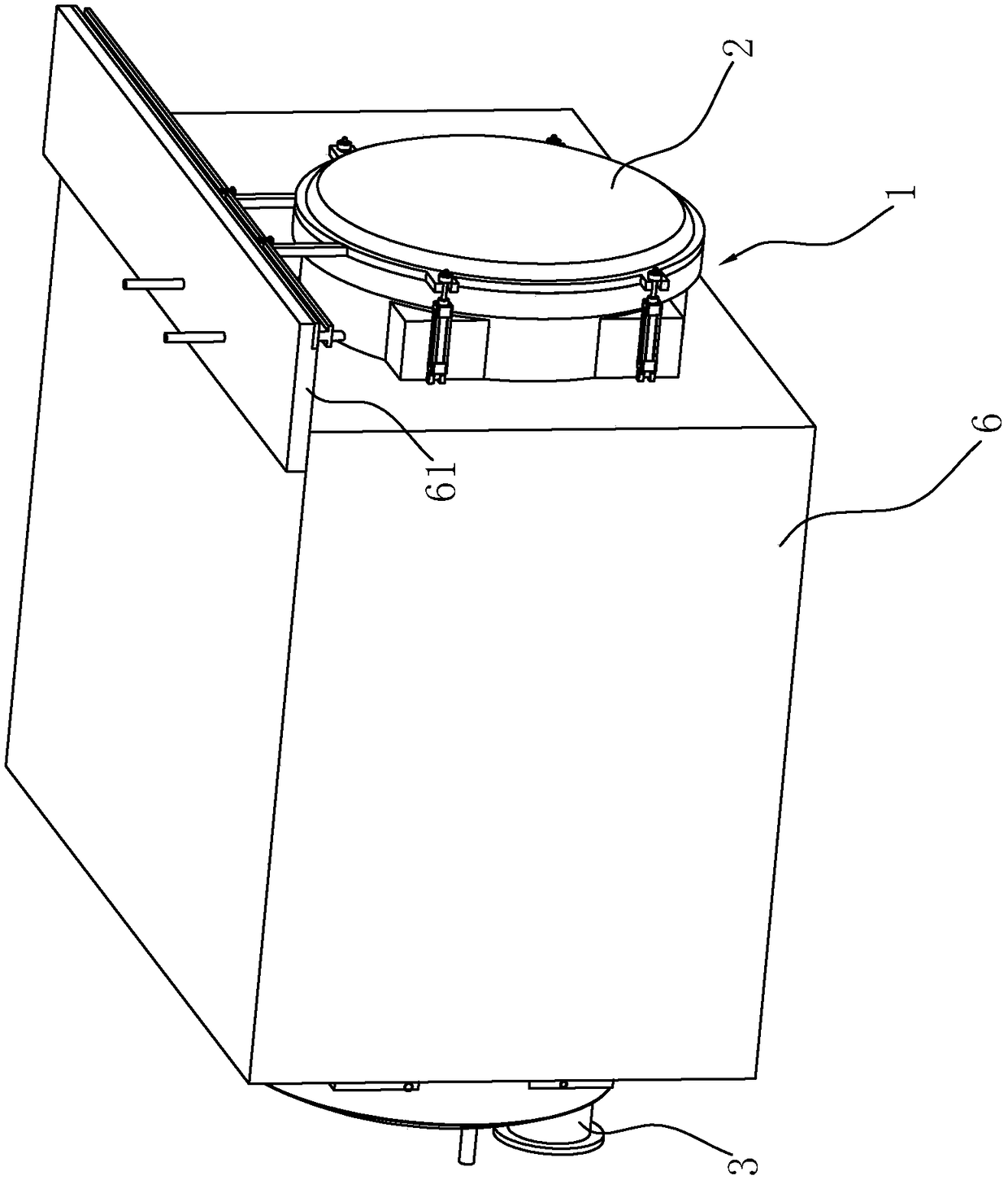
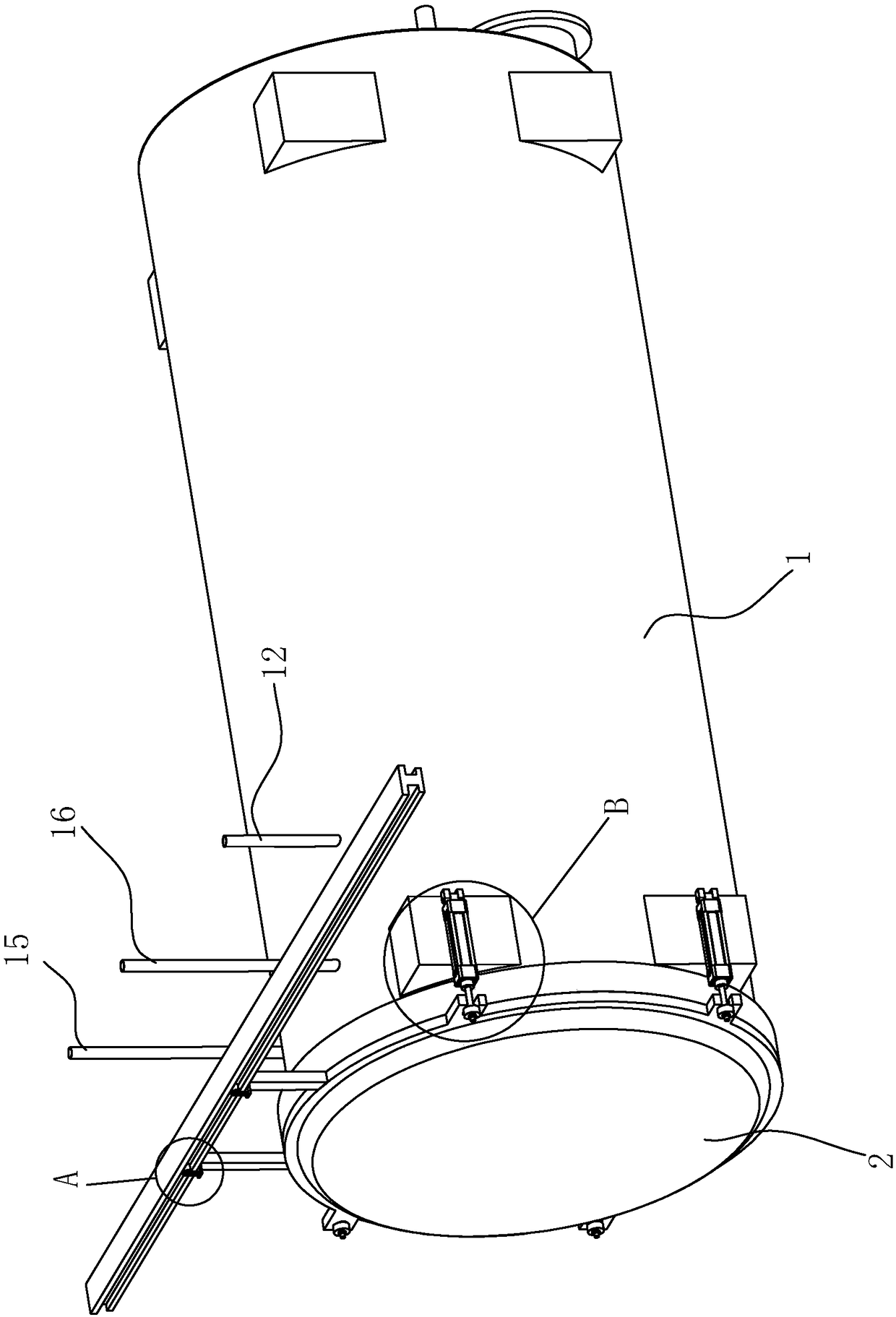
[0040] Embodiment 1: a kind of lyophilizer, such as figure 1 with Figure 5As shown, it includes a freeze dryer cylinder 1, a feed door 2 arranged at one end of the freeze dryer cylinder 1, and a water outlet 3 arranged at the other end of the freeze dryer cylinder 1, and the water outlet 3 is hinged with a water outlet; The freeze dryer cylinder 1 is provided with an ice-melting chamber and an ice-collecting chamber in sequence from the feed door 2 to the water outlet 3, and a partition 11 is arranged between the ice-melting chamber and the ice-collecting chamber, and the partition 11 and the freeze-drying machine cylinder The inner wall of the body 1 is fixedly connected, and a through hole connecting the ice-melting chamber and the ice-collecting chamber is opened on the partition 11; the side wall of the ice-melting chamber is connected with a vacuum tube 12 (such as figure 2 As shown), a vacuum pump is connected to the end of the vacuum tube 12 away from the ice-melting...

Embodiment 2

[0050] Embodiment 2: a kind of defrosting cycle system for the above-mentioned freeze dryer, such as Figure 10 As shown, it includes an ice-melting tank 8 arranged at the water outlet 3 of the lyophilizer cylinder 1, a heating circulation pipeline 9 connected to the air inlet pipe 15 and the air outlet pipe 16 on the lyophilizer cylinder 1, and a spray pipe 52 extends out of the ice-melting circulation pipeline 10 connected to one end of the lyophilizer cylinder 1; the heating circulation pipeline 9 is connected to the ice-melting circulation pipeline 10 through a plate heat exchanger 1001; the heating circulation pipeline 9 is connected to an air intake A check valve 92 is provided between the channel 91 , the inlet channel 91 and the plate heat exchanger 1001 , and an outlet channel 93 is connected between the check valve 92 and the plate heat exchanger 1001 .

[0051] One end of the ice-melting circulation pipeline 10 is arranged in the ice-melting tank 8, and the ice-melt...


PUM


Abstract

The invention discloses a freeze dryer which comprises a freeze dryer barrel, a feeding door, a door locking device and a water outlet, wherein the feeding door is arranged at one end of the freeze dryer barrel; the door locking device moves so as to prop the feeding door against the freeze dryer barrel; the water outlet is arranged at the other end of the freeze dryer barrel; the freeze dryer barrel is placed in a freezer; a feeding slide rail is fixedly connected with the top end of the inner wall of the freeze dryer barrel; a plurality of feeding plates are arranged in the freeze dryer, detachably connected together, and in slip connection with the feeding slide rail; an ice melting device and an ice collecting device are sequentially arranged in the freeze dryer barrel; and the ice melting device is close to the feeding door. According to the freeze dryer, the feeding plates are detachably connected together, so that corresponding connecting plates can be easily adopted for connecting the feeding plates according to the quantity of materials, and then the materials can be placed on the connecting plates; and through the slip connection between the connecting plates and the feeding slide rail, the feeding plates can be easily put into the freeze dryer barrel and easily mounted, and then the materials can be easily fed.

Description

technical field [0001] The invention relates to the field of freeze-drying equipment, in particular to a freeze-dryer and a defrosting circulation system for the freeze-dryer. Background technique [0002] Freeze dryer is a kind of freeze-drying equipment for freeze-drying materials with moisture. The freeze-dryer adopts a separate design of drying chamber and cold trap, and uses silicone oil as the heat transfer medium. [0003] The prior art can refer to the Chinese utility model patent whose authorized announcement number is CN201476521U, which discloses a hydraulic automatic locking device for the door of the freeze dryer. One-piece door frame flange, and the side of the door frame of the freeze dryer is equipped with a box flange, and the freeze dryer is equipped with a locking device, the locking device includes an oil cylinder, an oil cylinder rod, an oil cylinder connecting piece, and a door locking piece , The oil cylinder is fixedly connected with the flange of th...

Claims


Application Information

Patent Timeline
Patent Type & Authority Applications(China)
IPC IPC(8): F26B25/00
CPCF26B25/00F26B25/001
Inventor 邵平义韩显森郭树峰
Owner QINGDAO BORUI EQUIP MFG CO LTD
Why Eureka
Try Eureka