Ground fracture expansion simulation device and use method thereof

A technology of crack propagation and simulated ground, applied in the field of geotechnical engineering, can solve the problems of single type of basement fault and no consideration of boundary effects, etc., and achieve the effect of breaking through boundary effects, considering multiple factors, and simple operation process

Pending Publication Date: 2018-07-10
CHANGAN UNIV
View PDF0 Cites 17 Cited by
  • Summary
  • Abstract
  • Description
  • Claims
  • Application Information

AI Technical Summary

Problems solved by technology

[0003] The purpose of the present invention is to provide a device for simulating the propagation of ground fissures and its use method, which can solve the problem that the existing

Method used


Image

  • Ground fracture expansion simulation device and use method thereof
  • Ground fracture expansion simulation device and use method thereof
  • Ground fracture expansion simulation device and use method thereof

Examples


Embodiment 1

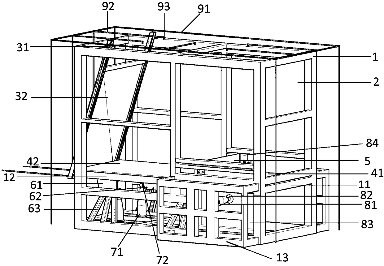
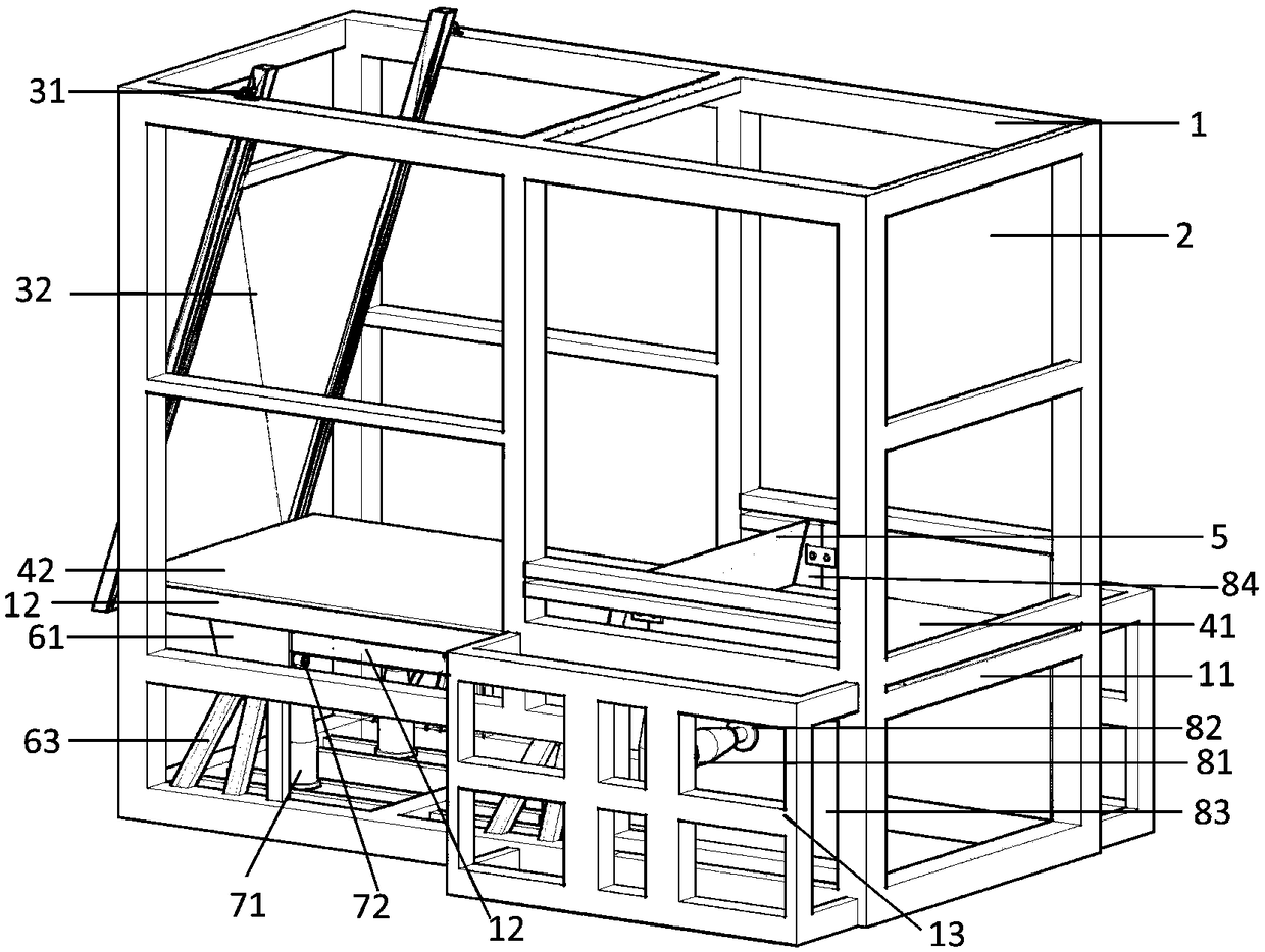
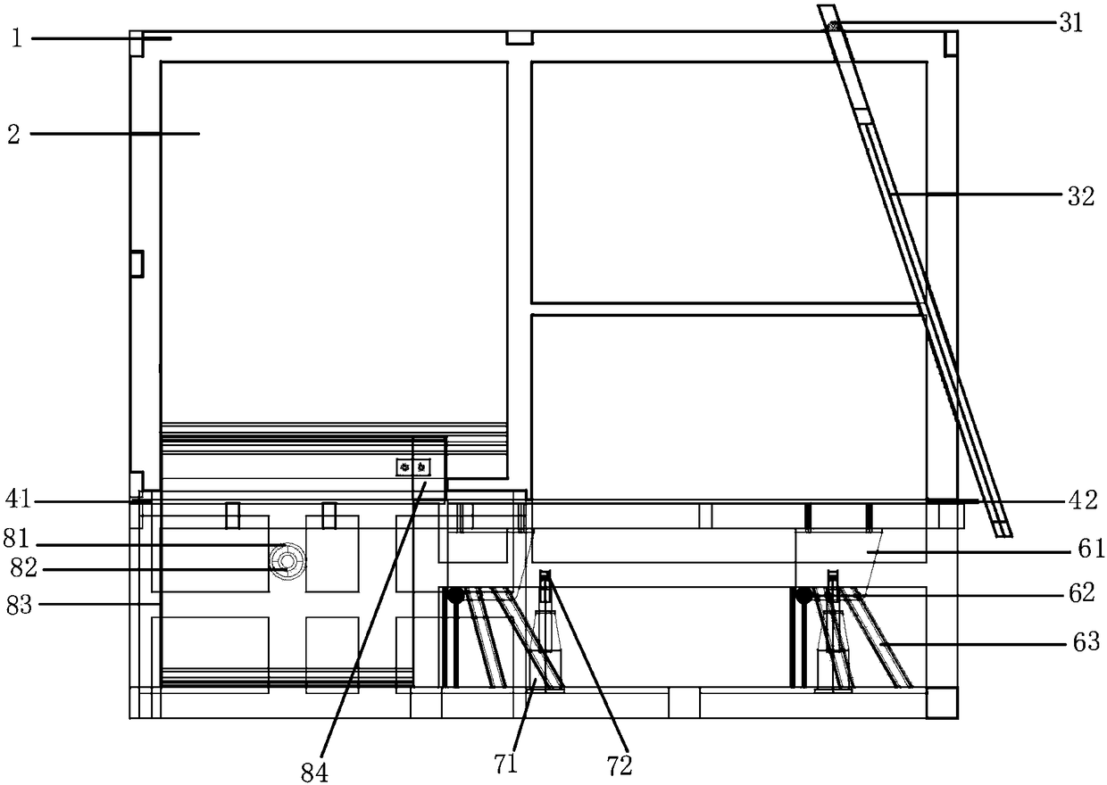
[0058] Working condition 1 (such as figure 1 ) implementation plan: ① Adjust the side wall loading device: No. 2 side wall steel plate with an installation angle of 90° (see Figure 7), and move the side wall steel plate to make it close to the frame to avoid its influence on the normal fault movement. holes and fixed with screws to simulate a normal fault with a dip angle of 90°. ③Adjust the inclination angle of the movable baffle: fix the position of the bearing in the screw hole closest to the baffle, and connect the baffle to the bearing with screws to ensure that the inclination angle of the baffle is also 90°, which ensures the consistency between the model boundary conditions and the actual boundary conditions resemblance. ④Install a smooth thin steel sheet with a thickness of 3mm between the support plate of the upper wall and the lower wall, and adjust the inclination angle of the thin steel plate to 90°, which is consistent with the inclination angle of the incline...

Embodiment 2

[0060] Working condition 2 implementation plan: ①Adjust the side wall loading device: install the No. 2 side wall steel plate with an angle of 75°, and move the side wall steel plate to make it close to the frame to avoid its influence on the movement of the normal fault. ②Adjust the tilt angle device : Insert one end of the guide rail roller into the inclined groove guide rail with an inclination angle of 75°, and the other end passes through the guide hole of the angle steel and fix it with screws to simulate a normal fault with an inclination angle of 75°. ③Adjust the inclination angle of the movable baffle: fix the position of the bearing in the pair of screw holes in the middle, and connect the baffle and the bearing with screws to ensure that the inclination angle of the baffle is also 75°, which ensures that the boundary conditions of the model are similar to the actual boundary conditions. ④ Install a 3mm thick mica sheet between the upper plate and the lower plate supp...

Embodiment 3

[0062] Implementation plan for working condition 3: ①Adjust side wall loading device: No. 2 side wall steel plate with an installation angle of 60° (see Figure 8 ), and move the side wall steel plate to make it close to the frame, so as to avoid its influence on the reverse fault movement. holes and fixed with screws to simulate a fault with a dip angle of 60°. ③Adjust the inclination angle of the movable baffle: fix the position of the bearing in the screw hole farthest from the baffle, and connect the baffle to the bearing with screws to ensure that the inclination angle of the baffle is also 60°, which ensures the boundary conditions of the model and the actual boundary conditions similar to. ④Install a smooth thin steel sheet with a thickness of 3mm between the support plate of the upper wall and the lower wall, and adjust the inclination angle of the thin steel plate to 60°, which is consistent with the inclination angle of the inclined groove guide rail and the baffle ...


PUM

PropertyMeasurementUnit
Thicknessaaaaaaaaaa
Thicknessaaaaaaaaaa

Abstract

The invention belongs to the field of geotechnical engineering, and relates to a ground fracture expansion simulation device and a use method thereof. The ground fracture expansion simulation device comprises a framework, an observation window, a baffle plate, a lower disc support plate, an upper disc support plate, a preserved fracture, a variable-inclination-angle device, a bottom loading deviceand a side wall loading device, wherein an artificial portable rainfall device can also be arranged on the top of the framework; the artificial portable rainfall device controls the rainfall quantitythrough a flow rate measuring instrument. The loading device comprises a bottom loading device and a side wall loading device. The bottom layer base rock in a model box can simulate the influence ofthe positive and reverse fault movement, strike-slip fault movement, strike-slip positive fault movement and strike-slip negative fault movement on the upside covering soil body. In addition, the method has the advantages that the operation process is simple and convenient; economic performance is realized; considered factors are various; the problems of single substrate movement type, movement inclination angle change incapability, obvious boundary effects, rainfall influence ignoring and the like in an ordinary simulation experiment can be overcome.

Description

technical field [0001] The invention belongs to the field of geotechnical engineering, and relates to a device for simulating the expansion of ground fissures and a use method thereof, in particular to a device suitable for simulating the influence of rock-soil fractures on overlying soil bodies and a use method thereof. Background technique [0002] At present, in the construction process of various rock and soil engineering, people are more and more inclined to rely on indoor physical model tests to simulate the evolution of various stress fields inside rock and soil, and finally get the desired conclusions and parameters. However, some physical model test devices can only simulate fault movement and cannot observe the rupture law of the overlying soil, such as two inventions submitted by Huaqiao University: a pressurized strike-slip fault dislocation simulation device and simulation experiment method and a Oblique sliding fault simulation device and simulation method, alt...

Claims


Application Information

Patent Timeline
IPC IPC(8): G01N33/24G01N3/06
CPCG01N3/06G01N33/24G01N2203/0682G01N2203/0676G01N2203/0066
Inventor 马润勇潘爱芳巩云鹏杜岳洋孙长明李焱马学军
Owner CHANGAN UNIV
Why Eureka
Try Eureka