Casting method for preventing shrinkage porosity at thick large wall of casting

A technology for castings and defects, which is applied in the casting field to prevent shrinkage and porosity defects at thick and large walls of castings. Light weight, large heat capacity ratio, and the effect of solving porosity

Active Publication Date: 2018-07-13
KOCEL EQUIP
View PDF9 Cites 6 Cited by
  • Summary
  • Abstract
  • Description
  • Claims
  • Application Information

AI Technical Summary

Problems solved by technology

[0004] The present invention overcomes the fact that the cold iron used in the existing molding method cannot be fixed, and it is easy to move and move during the molding vibration process, which makes it impossible to feed the thick and large wall of the casting, and the cold iron used in the existing molding method is relatively heavy. Due to the problem of easy damage and deformation to the pattern, a casting method is provided to prevent shrinkage and porosity defects at the thick and large walls of the casting. Porosity and shrinkage of thick-walled parts during the process

Method used


Image

  • Casting method for preventing shrinkage porosity at thick large wall of casting
  • Casting method for preventing shrinkage porosity at thick large wall of casting
  • Casting method for preventing shrinkage porosity at thick large wall of casting

Examples


Embodiment 1

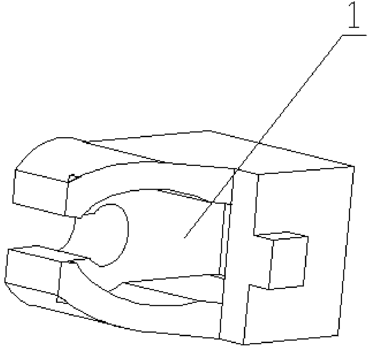
[0022] Such as Figure 1 to Figure 3 As shown, a casting method to prevent shrinkage and porosity at the thick and large wall of the casting. The casting method adopts the lost foam casting process, and the molding process adopts the vacuum negative pressure molding method. The cold iron of the chilling material is placed at the corresponding position of the lost pattern according to the requirements of the casting process, and the cold iron and the lost pattern are bonded together. The light chilling material is graphite.

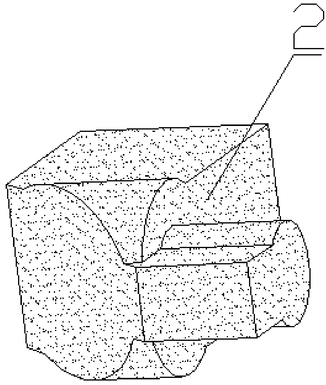
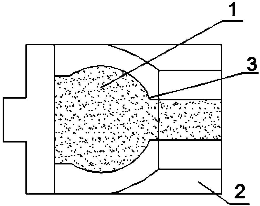
[0023] When the thick and large wall of the casting is the jaw structure 1, graphite is selected as the light chilling material, and it is designed as a jaw graphite chiller 2 structure that fits with the jaw structure 1, and the jaw graphite chiller 2 and the corresponding After assembling the jaw structure 1 of the lost pattern shape, use hot melt adhesive 3 to bond the gap between the jaw graphite cold iron 2 and the lost pattern shape. After the hot me...

Embodiment 2

[0025] Such as Figure 4 to Figure 6 As shown, when the thick and large wall of the casting is a planar structure 4, graphite is selected as a light chilling material, and it is designed as a rectangular graphite chiller 5 structure. After applying and drying the lost foam pattern in sequence, the rectangular graphite The cold iron 5 is placed on the thick and large-walled planar structure 4 of the lost foam pattern according to the requirements of the casting process, and the cold iron and the lost foam pattern are bonded with the sand mold adhesive 6, and the sand mold adhesive 6 is hardened and molded.


PUM

PropertyMeasurementUnit
densityaaaaaaaaaa

Abstract

The invention provides a casting method for preventing shrinkage porosity at a thick large wall of a casting. The casting method comprises the steps that an evaporative pattern casting technology is adopted, a vacuum negative pressure molding method is adopted in the molding procedure, before an evaporative pattern is subjected to vacuum negative pressure molding, a chiller made from a light chillmaterial is placed in a corresponding position of the evaporative pattern according to the requirement of the casting technology, and the chiller and the evaporative pattern are bonded together. According to the casting method, the problems that the chiller utilized in a conventional molding method cannot be fixed and is liable to move during the molding compaction process, feeding cannot be carried out on the thick large wall of the casting, the chiller utilized in the conventional molding method is relatively heavy, and the pattern is liable to damage and deform are solved, the casting method for preventing shrinkage porosity at the thick large wall of the casting is provided, technological methods of adopting the light chill material and assembling the chiller in advance are adopted, and porosity and shrinkage cavity problems of the thick wall during the casting process are effectively solved.

Description

technical field [0001] The invention relates to the technical field of vacuum negative pressure lost foam casting, in particular to a casting method for preventing shrinkage and porosity defects at thick and large walls of castings. Background technique [0002] Lost foam casting is a casting method that replaces the mold with a foam plastic mold. The mold is not taken out, and the molten metal is poured directly. The molten metal burns and loses the mold to obtain an ideal casting. This casting technology uses low-density lost foam materials as raw materials, such as EPS / STMMA, and the surface is coated with paint to build strength and then filled with sand. [0003] The vacuum negative pressure molding method refers to a green casting method that uses dry sand to bury the box for molding, uses a sealed vacuum to make the dry sand build strength around the pattern, and then pours it into shape. The pattern surface of this casting method cannot place moving process informat...

Claims


Application Information

Patent Timeline
Patent Type & Authority Applications(China)
IPC IPC(8): B22C9/04B22D15/00
CPCB22C9/046B22D15/00
Inventor 潘凤英扈广麒杨争光戴海燕张海霞
Owner KOCEL EQUIP
Why Eureka
Try Eureka