Engine cylinder cover deburring assembly

An engine cylinder head and deburring technology, which is applied in the directions of grinding machine parts, grinding frames, grinding feed motion, etc., can solve the problems of reduced product production efficiency, low work efficiency, troublesome operation, etc. Manual operation, improve deburring efficiency, and achieve the effect of cleaning operations

Pending Publication Date: 2018-07-13
无锡市苏文自动化科技有限公司
View PDF0 Cites 1 Cited by
  • Summary
  • Abstract
  • Description
  • Claims
  • Application Information

AI Technical Summary

Problems solved by technology

It can be seen from the above description that the existing deburring method starts from the entry of the workpiece, the processing of the workpiece, and the output of the workpiece are all completed by manual operation, the work efficiency is very low, the labor output ratio does not meet the requirements of modern enterprises, and the operating skills of workers The requirements are high, and the lifting of the workpiece requires professional operation
In addition, because there are too many holes to be processed and the sizes are not equal, the operation is more troublesome, and the phenomenon of missing processing is easy to occur, which affects the post-processing
At the same time, the quality of products processed by hand is uneven, and it cannot be quickly connected with the assembly line to achieve full assembly line operation, thereby reducing the production efficiency of the product

Method used


Image

  • Engine cylinder cover deburring assembly
  • Engine cylinder cover deburring assembly
  • Engine cylinder cover deburring assembly

Examples


Embodiment Construction

[0027] The specific implementation manners of the present invention will be further described in detail below in conjunction with the accompanying drawings and embodiments. The following examples are used to illustrate the present invention, but are not intended to limit the scope of the present invention.

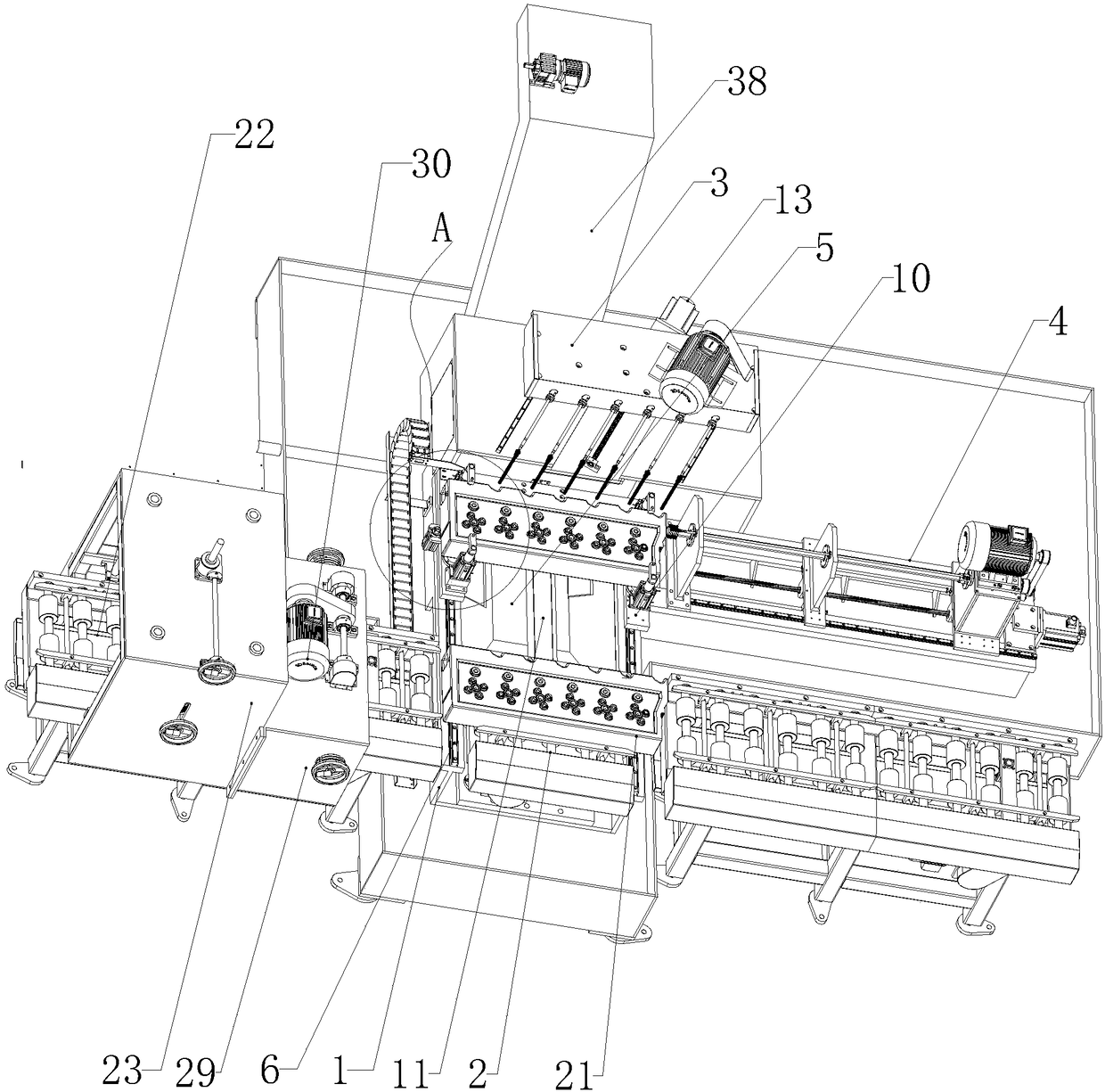
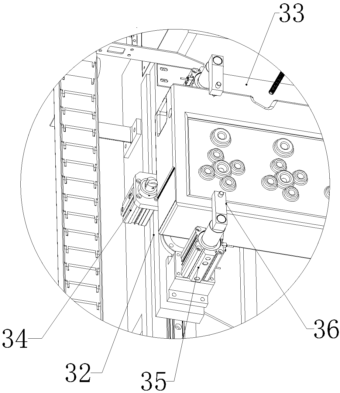
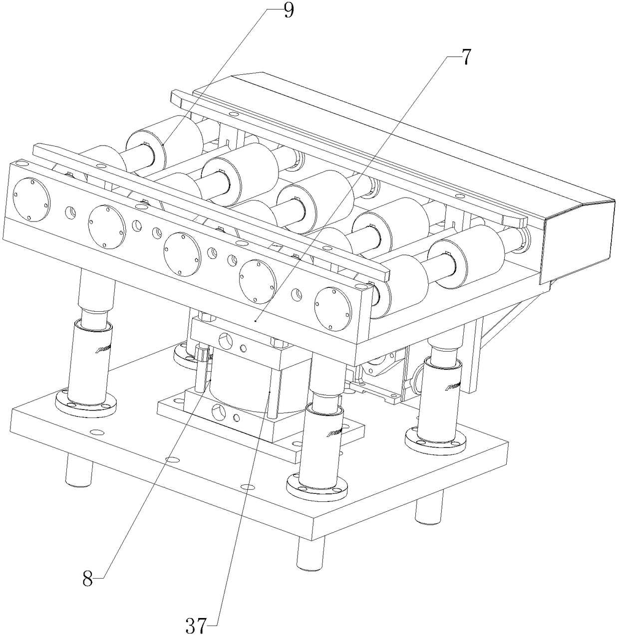
[0028] see Figure 1 to Figure 8 , a deburring assembly for an engine cylinder head according to a preferred embodiment of the present invention, comprising a body 1, a lifting roller table device 2 arranged at the front end of the body, an inclined oil channel power head 3 arranged at the rear end of the body, and a rear The long oil channel power head 4, the bottom of the body is provided with a chip discharge port 5, the left and right sides of the body surface are provided with guide rails 6, and the lifting roller table device includes a lifting platform 7 above the bottom wall of the body, a driving lifting platform The lifting driving device 8 for lifting, the lift...


PUM


Abstract

The invention relates to an engine cylinder cover deburring assembly. The engine cylinder cover deburring assembly comprises an engine body, a lifting roller way device, an inclined oil passage powerhead and a long oil passage power head. Guide rails are arranged on the left side and the right side of the surface of the engine body. The lifting roller way device comprises a lifting table arrangedon the upper portion of the bottom wall of the engine body, a lifting driving device for driving the lifting table to rise and fall, and lifting guide rollers arranged above the lifting table. A C-shaped seat is further arranged on the surface of the engine body, and a C-shaped seat driving device for driving the C-shaped seat to move along the guide rails is further arranged on the engine body.The inclined oil passage power head comprises an inclined oil passage power head box, an inclined oil passage power head box driving device for driving the inclined oil passage power head box to move,inclined oil passage brush rods parallelly arranged on the inclined oil passage power head box, and an inclined oil passage brush rod driving device for driving the inclined oil passage brush rods torotate. The long oil passage power head comprises a mounting seat, a long oil passage power head box, a long oil passage power head box driving device, a long oil passage brush rod and supporting plates. The engine cylinder cover deburring assembly is high in deburring efficiency and good in effect.

Description

technical field [0001] The invention relates to an engine deburring device, in particular to an engine cylinder head deburring assembly. Background technique [0002] After the engine is formed, there are generally some burrs in each oil passage hole, and the operator needs special equipment to deburr it for the next step of processing. The existing mode of deburring the engine block and the cylinder head is mainly realized by manual operation. Firstly, the operator lifts the workpiece to the operating station through the elevator. After the workpiece is in place, the operator holds the wind gun and holds the brush rod, and then extends the end of the brush rod into the oil passage hole to be processed in the cylinder block and cylinder head. The brush rod is reciprocated in the processing holes such as the main shaft hole, etc., to deburr and rust the processing parts. Due to the different machining apertures of workpieces, operators often need to replace brushes with cor...

Claims


Application Information

Patent Timeline
Patent Type & Authority Applications(China)
IPC IPC(8): B24B9/04B24B41/00B24B41/02B24B41/06B24B27/00B24B47/14B24B47/12
CPCB24B9/04B24B27/0023B24B27/0076B24B41/005B24B41/02B24B41/06B24B47/12B24B47/14
Inventor 左苏松
Owner 无锡市苏文自动化科技有限公司
Why Eureka
Try Eureka