Eureka AIR delivers breakthrough ideas for toughest innovation challenges, trusted by R&D personnel around the world.

Injection mold for continuous injection molding of products of different shapes and machining method thereof

A technology for injection molds and products, applied in the field of injection molding machines, can solve the problems of increasing the management workload of injection molds, waste of production costs, etc., and achieve the effects of reasonable structure design, reduction of production costs, and high processing efficiency.

Pending Publication Date: 2018-07-13
太仓朗盛金属制品有限公司
View PDF2 Cites 0 Cited by
  • Summary
  • Abstract
  • Description
  • Claims
  • Application Information

AI Technical Summary

Problems solved by technology

[0002] Injection mold is a tool for producing plastic products, and it is also a tool for giving plastic products a complete structure and precise dimensions. It is used in industrial production for injection molding, blow molding, extrusion, die-casting or stamping. This kind of mold, during injection molding, mainly realizes the processing of the shape of the article through the change of the physical state of the molding material. During injection molding, the mold is clamped on the injection molding machine, and the molten plastic is injected into the molding cavity, and is cooled and shaped in the cavity. Then the upper and lower molds are separated, and the product is ejected from the cavity through the product ejection mechanism to leave the mold. Because the structure of plastic products is complicated and simple, the types and structures of injection molds are also varied. In practical applications, If products with different shapes are injected, the types of injection molds will increase, which will not only cause waste of production costs, but also increase the workload of injection mold management

Method used


Image

  • Injection mold for continuous injection molding of products of different shapes and machining method thereof

Examples


Embodiment Construction

[0014] The present invention will be further explained below in conjunction with the accompanying drawings and specific embodiments.

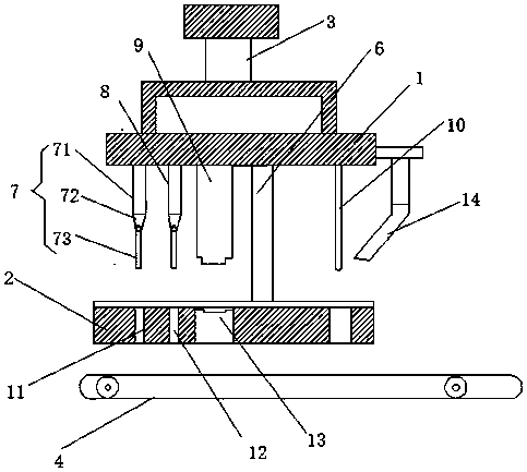
[0015] Such as figure 1 Shown is an injection mold for continuous injection of products of different shapes, an upper mold base 1, a lower mold base 2 and a mold clamping cylinder 3, the upper mold base 1 is connected to the mold clamping cylinder 3, and the lower mold base 2 is provided with Horizontal conveying guide rail 4, the middle position on the upper mold base 1 is fixedly provided with intermediate guide column 6, and the left side of intermediate guide column 6 is provided with punching thimble one 7, punching thimble two 8 and stamping punch 9, and intermediate guide column 6 The right side is provided with a bending thimble 10, and the lower mold base 2 is provided with an injection flow channel 21, and the injection flow channel 21 is provided with thimbles corresponding to the positions of the punching thimble 1 7 and the punchin...


PUM


Abstract

The invention discloses an injection mold for continuous injection molding of products of different shapes. The injection mold comprises an upper mold seat, a lower mold seat and a mold-closing oil cylinder; the upper mold seat is connected with the mold-closing oil cylinder; a horizontal conveying guide rail is arranged below the lower mold seat; a middle guiding column is fixedly arranged in themiddle on the upper mold seat, a first punching ejector pin, a second punching ejector pin and a stamping male mold are arranged on the left side of the middle guiding column, and a bending ejector pin is arranged on the right side of the middle guiding column; an injection molding flow channel is formed in the lower mold seat; and a first ejector pin through hole, a second ejector pin through hole and a stamping hole are formed in the injection molding flow channel, wherein the first ejector pin through hole and the second ejector pin through hole correspond to the first punching ejector pinand the second punching ejector pin in position, and the stamping hole corresponds to the stamping male mold. Injection molding materials injected into the injection molding flow channel are subjected to punching machining, punching forming and bending treatment forming, the injection molded products of the different shapes are machined through the injection mold, the machining efficiency is high, and the production cost is reduced.

Description

technical field [0001] The invention relates to the technical field of injection molding machines, in particular to an injection mold for continuously molding products of different shapes and a processing method thereof. Background technique [0002] Injection mold is a tool for producing plastic products, and it is also a tool for giving plastic products a complete structure and precise dimensions. It is used in industrial production for injection molding, blow molding, extrusion, die-casting or stamping. This kind of mold, during injection molding, mainly realizes the processing of the shape of the article through the change of the physical state of the molding material. During injection molding, the mold is clamped on the injection molding machine, and the molten plastic is injected into the molding cavity, and is cooled and shaped in the cavity. Then the upper and lower molds are separated, and the product is ejected from the cavity through the product ejection mechanism...

Claims


Application Information

Patent Timeline
IPC IPC(8): B29C45/26B29C45/72B29C69/02
CPCB29C45/0053B29C45/26B29C45/2628B29C45/7207
Inventor 夏继文
Owner 太仓朗盛金属制品有限公司
Why Eureka
Eureka Blog
Learn More