Supercharge Your Innovation With Domain-Expert AI Agents!

Multi-rotor unmanned aerial vehicle emergency stop device and method

A multi-rotor unmanned aerial vehicle, emergency shutdown technology, applied in the field of unmanned aerial vehicles, can solve the problems of potential safety hazards and easy flipping of the body, and achieve the effect of preventing continuous high-speed rotation

Inactive Publication Date: 2018-07-13
黄昭林
View PDF0 Cites 3 Cited by
  • Summary
  • Abstract
  • Description
  • Claims
  • Application Information

AI Technical Summary

Problems solved by technology

When falling, generally, a certain rotor assembly will hit the ground or other objects first, but because the rotor assembly is still under the control of high-speed rotation, the entire body is prone to flipping, causing other rotor assemblies to also be powered Collisions continue to occur in the state of high-speed rotation, and there are great potential safety hazards for the UAV itself and personal safety.

Method used


Image

  • Multi-rotor unmanned aerial vehicle emergency stop device and method
  • Multi-rotor unmanned aerial vehicle emergency stop device and method
  • Multi-rotor unmanned aerial vehicle emergency stop device and method

Examples


Embodiment 1

[0039] Reference figure 1 This embodiment provides an emergency shutdown device for a multi-rotor drone, which includes several speed sensors, a number of controllable switches, and independent control modules; wherein, a number of speed sensors are installed in the rotor assembly of the multi-rotor drone. To detect the rotation speed of the rotor assembly and output the rotation speed signal (V1-V4); the controllable switch is a normally closed switch, such as a magnetic latching relay, which is connected in series between the rotor assembly and the controller of the multi-rotor UAV; The sensor and several controllable switches are electrically connected with the independent control module; the independent control module is installed in the body of the multi-rotor drone.

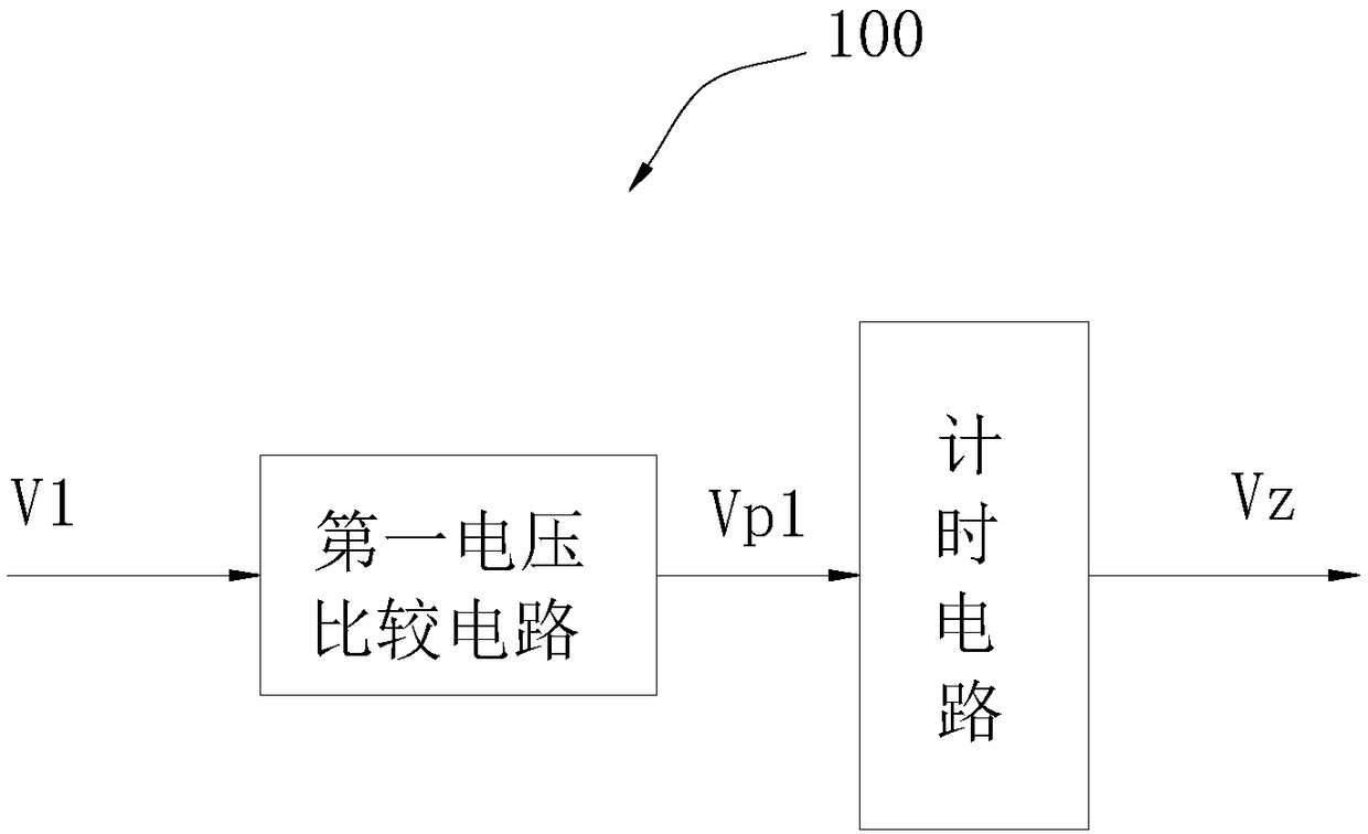
[0040] The independent control module includes a flight detection circuit 100, a synchronization detection circuit 200, and a drive circuit 300. Among them, the flight detection circuit 100 has an input termina...

Embodiment 2

[0046] Based on the first embodiment, this embodiment provides an emergency shutdown method for a multi-rotor drone, including:

[0047] S1. Determine whether the multi-rotor drone enters the flying state according to the output signal of one of the speed sensors, and output a corresponding state detection signal.

[0048] Specifically, when the time for which the output signal of one of the rotational speed sensors exceeds the first preset value exceeds the preset time period, it is determined that the flight state is entered.

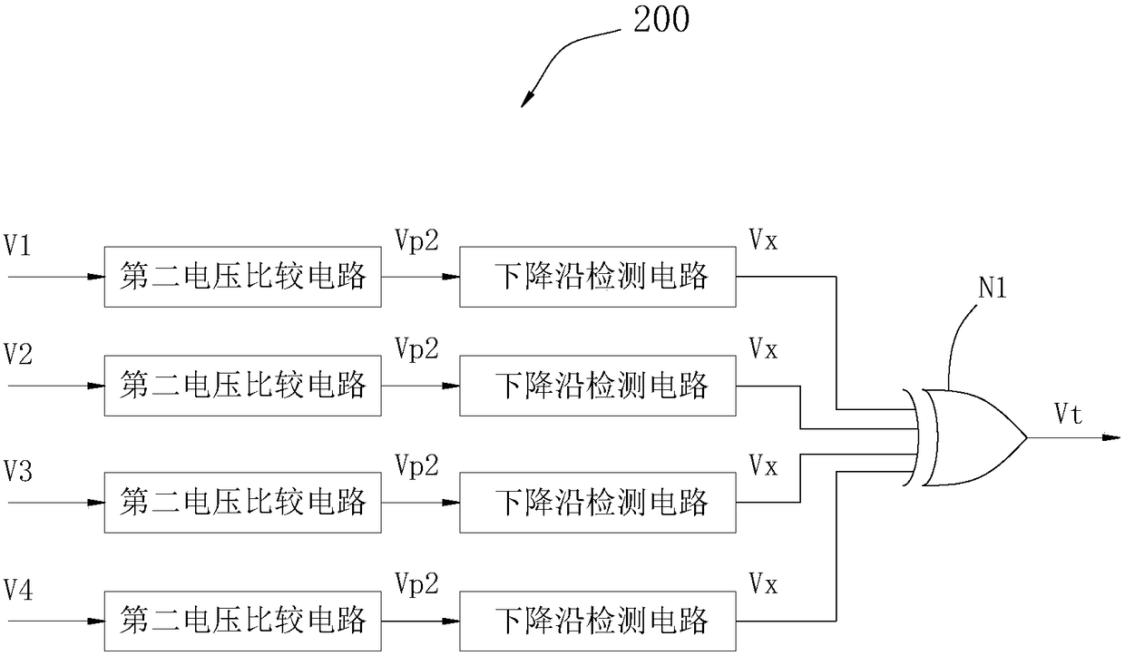
[0049] S2. Output a corresponding synchronization detection signal according to the change of the output signal of each speed sensor; where the change refers to whether the change of the output signal of each speed sensor is synchronized.

[0050] S3. Perform a logical operation on the received state detection signal and the synchronization detection signal according to the preset operation logic, and control the controllable switch according to the operation ...


PUM


Abstract

The invention discloses a multi-rotor unmanned aerial vehicle emergency stop device and method; the device comprises a plurality of speed sensors, a plurality of controllable switches and an independent control module, wherein the speed sensors are mounted in rotor components of a multi-rotor unmanned aerial vehicle and are used for detecting speed of the rotor components; the controllable switches are normally closed switches serially connected between the rotor components and a multi-rotor unmanned aerial vehicle controller; both the speed sensors and the controllable switches are electrically connected with the independent control module; the independent control module is mounted in a body of the multi-rotor unmanned aerial vehicle; the independent control module includes a flight detection circuit, a synchronous detection circuit and a driving circuit. The flight detection circuit and a synchronous detection circuit judge whether the multi-rotor unmanned aerial vehicle needs emergency stop; the driving circuit is used to perform stop controlling. The multi-rotor unmanned aerial vehicle emergency stop device and method can partly provide automatic emergency stop, thus preventingthe rotor components from continuously rotating at high speed in powered state after being impacted.

Description

Technical field [0001] The present invention relates to the technical field of unmanned aerial vehicles, in particular to an emergency shutdown device and method for multi-rotor unmanned aerial vehicles. Background technique [0002] UAV is abbreviated as UAV, which refers to an aircraft that can fly autonomously or remotely without an operator. Multi-rotor UAV is a special unmanned helicopter with three or more rotor shafts, which passes through each axis. The motor on the rotor rotates to drive the rotor to generate lift and thrust. The total pitch of the rotor is fixed, not variable like a normal helicopter. By changing the relative speed between the different rotors, the uniaxial propulsion can be changed to control the aircraft. The running track. [0003] Through market research, it is found that multi-rotor drones often fall due to loss of control. In a fall, under normal circumstances, a certain rotor component will first collide with the ground or other objects, but beca...

Claims


Application Information

Patent Timeline
Patent Type & Authority Applications(China)
IPC IPC(8): G05B19/042
CPCG05B19/0423G05B2219/25257
Inventor 黄昭林
Owner 黄昭林
Features
  • R&D
  • Intellectual Property
  • Life Sciences
  • Materials
  • Tech Scout
  • Unparalleled Data Quality
  • Higher Quality Content
  • 60% Fewer Hallucinations
Learn More