Working machine driving unit

A technology for driving devices and working machines, which is applied in the direction of fluid pressure actuating devices, mechanical equipment, and motor speed or torque control. The effect of eliminating pressure loss and throttling loss

Inactive Publication Date: 2005-10-19
CATEPILLAR SARL
View PDF1 Cites 20 Cited by
  • Summary
  • Abstract
  • Description
  • Claims
  • Application Information

AI Technical Summary

Problems solved by technology

[0010] The hydraulic excavator described in the bulletin, in the same Figure 10 Compared with the prior art shown, although the engine can be operated with better efficiency, since the circuits for driving the hydraulic actuators are independent, the remaining energy is obtained between the driving circuits of the hydraulic actuators. Less than effective use

Method used


Image

  • Working machine driving unit
  • Working machine driving unit
  • Working machine driving unit

Examples


Embodiment Construction

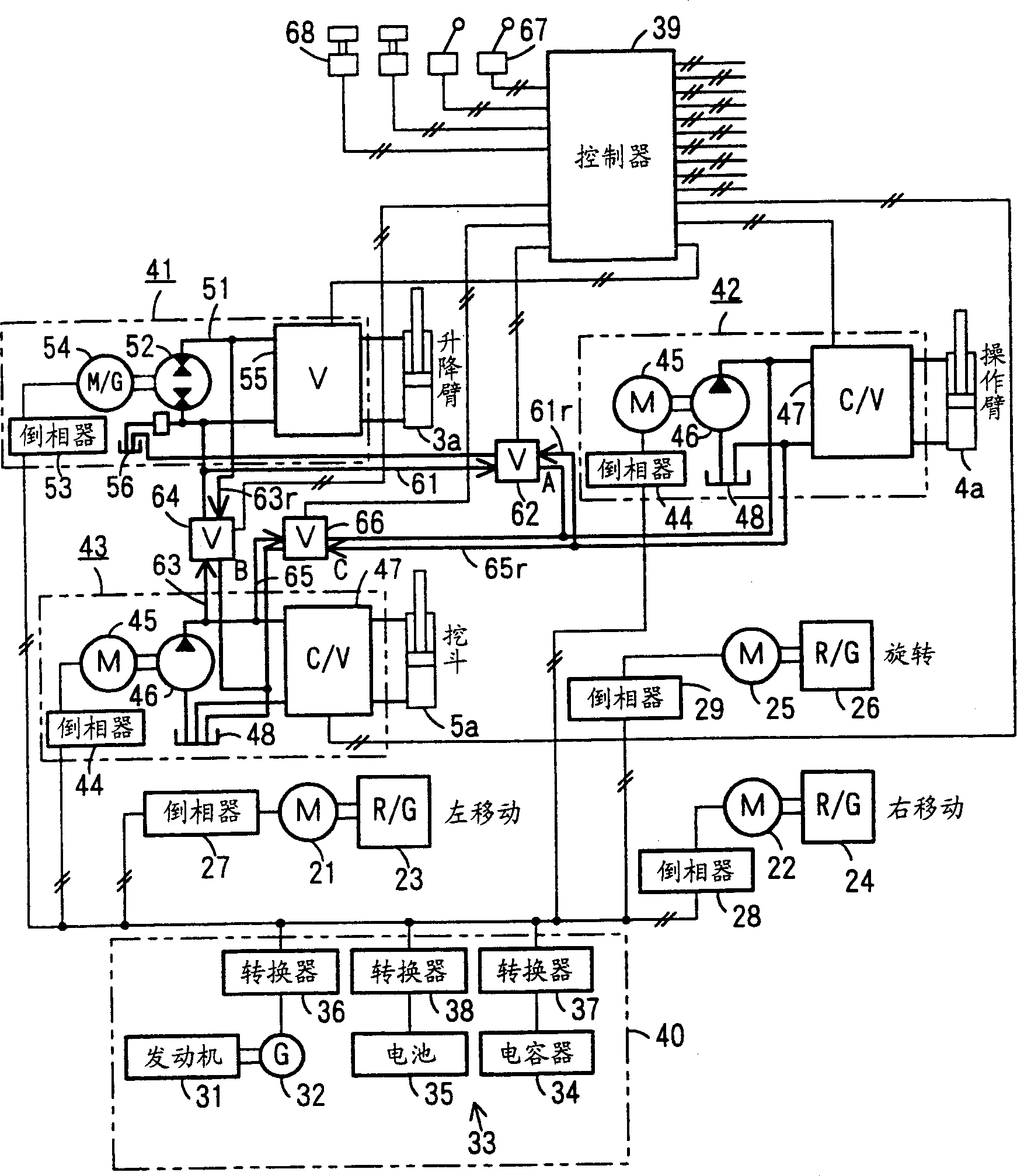
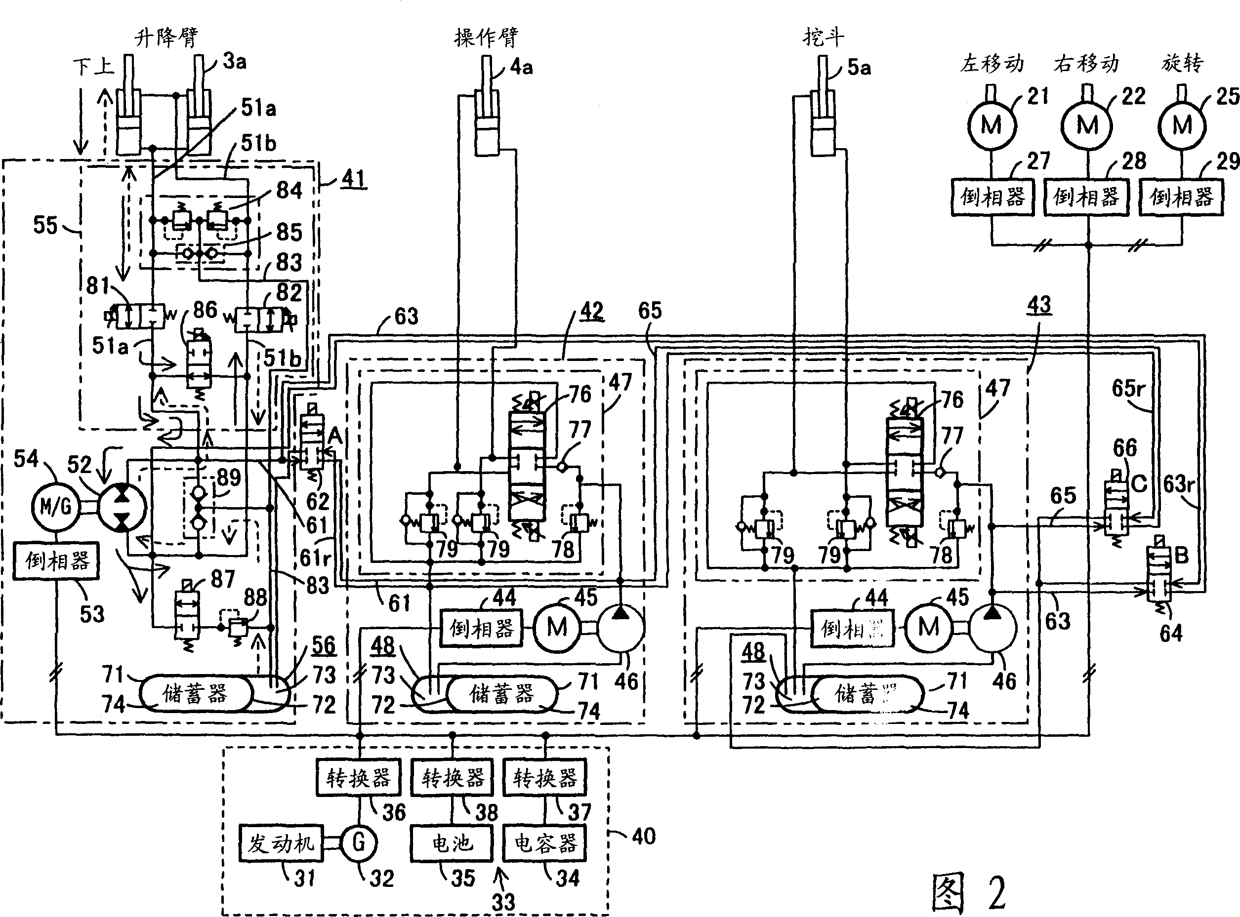
[0031] Below, combine Figure 1 to Figure 3 The first embodiment shown, Figure 4 The second embodiment shown, Figure 5 The third embodiment shown, Figure 6 and Figure 7 The fourth embodiment shown, and Figure 8 The shown fifth embodiment describes the present invention in detail. In addition, about Figure 9 The description of the shown hydraulic excavator is also used in the description of the present invention.

[0032] figure 1 Indicates the first embodiment of the driving device of the working machine, such as Figure 9 As shown, the working machine is a hydraulic excavator as a construction machine having a working device 6 that sequentially connects an elevating arm 3 , an operating arm 4 , and a bucket 5 . figure 1 Represent the circuit diagram of the composite driving device with the lifting arm-operating arm-digging bucket-compound circuit of the hydraulic excavator, and Fig. 2 shows the circuit diagram using figure 1 The circuit diagram shown is a more...


PUM


Abstract

A driving device of a work machine includes a power generator adapted to be driven by an engine, and a power storage device for storing the electric power generated by the power generator. Electric motors and a motor generator, both adapted to be operated by electric power supplied from either one or both of the power generator and the power storage device respectively drive pumps and a pump motor. Supporting circuits for feeding supporting hydraulic oil are provided between a plurality of driving circuits that drive a plurality of hydraulic actuators of a working unit by oil hydraulics generated by the pumps and the pump motor. By enabling the plurality of driving circuits to effectively share excess energy, the invention makes possible a compact construction of a driving device of a work machine.

Description

technical field [0001] The present invention relates to a driving device for a working machine such as a hydraulic excavator having a power source combining an engine and a generator. Background technique [0002] Figure 9 and Figure 10 shows the structure of the prior art, Figure 9 It is a figure showing the structure of a hydraulic excavator, Figure 10 is a circuit diagram showing the configuration of the hydraulic system. [0003] exist Figure 9 Among them, the upper rotating body 2 and the lower running body 1 form a rotatable combination, and the upper rotating body 2 is equipped with a working device 6. The working device 6 has: a lifting arm 3, which is installed on the upper rotating body 2 by swinging freely. The operating arm 4 is driven by the operating arm cylinder 4a swingably installed on the front end of the lifting arm 3; and the bucket 5 is driven by the bucket cylinder 5a installed on the front end of the operating arm 4. [0004] Such as Figure 1...

Claims


Application Information

Patent Timeline
Patent Type & Authority Applications(China)
IPC IPC(8): E02F9/00E02F9/20E02F9/22F15B11/16F15B11/17F15B15/18F15B21/14H02P5/00
CPCF15B11/17F15B2211/20561F15B2211/2658F15B2211/315F15B21/14F15B2211/7135F15B2211/20515E02F9/2075E02F9/2217F15B2211/20538E02F9/2025E02F9/2242F15B2211/20576F15B2211/7142F15B2211/20569
Inventor 三木正俊的场信明
Owner CATEPILLAR SARL
Why Eureka
Try Eureka