Rotating electrical machine and method for manufacturing rotating electrical machine

a technology of rotating electrical machines and electric motors, which is applied in the direction of manufacturing stator/rotor bodies, magnetic circuit rotating parts, and shape/form/construction of magnetic circuits, etc., can solve problems such as damage to rotary electric machines, and achieve the effect of inhibiting a reduction in the performance of rotary electric machines

Inactive Publication Date: 2012-01-12
HONDA MOTOR CO LTD
View PDF9 Cites 18 Cited by
  • Summary
  • Abstract
  • Description
  • Claims
  • Application Information

AI Technical Summary

Benefits of technology

[0006]The present invention has been made in view of the above problems. It is an object of the present invention to provide a rotary electric machine which is capable of efficiently transmitting a torque from a shaft to a ring core and also of preventing itself from contacting a stator while the rotary electric machine is rotating at a high speed, and a method of manufacturing such a rotary electric machine.
[0008]According to the present invention, the ring core is secured to the shaft by pressing the tapered surface of the plate-side tapered portion which is progressively wider toward the shaft and the tapered surface of the shaft-side tapered portion which is progressively wider toward the divided core plates, against each other. Therefore, a torque can efficiently be transmitted from the shaft to the ring core. Even when the rotary electric machine rotates at a high speed, applying centrifugal forces to the ring-shaped core plates, the ring-shaped core plates are prevented from increasing in diameter. Consequently, the rotary electric machine is capable of performing as desired while rotating at a high speed.
[0009]The plate-side tapered portions may be disposed in phase with the magnets. Since the plate-side tapered portion is held in press-contact with the shaft-side tapered portion, the position in phase with the plate-side tapered portion is relatively hard to displace while the rotary electric machine is in rotation. Consequently, the rotary electric machine is prevented from being damaged due to contact with the stator while the rotary electric machine is in high speed rotation.
[0011]Each of an angle formed between two slant lines interconnecting upper and lower bottoms of the plate-side trapezoidal region and an angle formed between two slant lines interconnecting upper and lower bottoms of the shaft-side trapezoidal region may be in the range from 60° to 120° inclusive. The angle which is equal to or greater than 60° makes it easy to inhibit the relative displacement between the plate-side tapered portion and the shaft-side tapered portion and the displacement of the ring-shaped core plates with respect to the shaft while the rotary electric machine is in rotation. The angle which is equal to or smaller than 120° makes it easy to fit the ring-shaped core plates over the shaft.
[0015]The pin holes may be disposed in positions which are spaced from the magnet insertion holes by the thickness of one magnet. It is thus possible to inhibit a reduction in the performance of the rotary electric machine.
[0016]Each of the ring-shaped core plates may have a plurality of dowels deformed along the directions in which the ring-shaped core plates are stacked, the dowels may be disposed along a circle that is concentric to the rotational axis of the shaft, and have a U-shaped cross section along lines tangential to the circle, and the dowels may have longitudinal directions parallel to the lines tangential to the circle. The ring-shaped core plates are thus prevented from being deformed while the rotary electric machine is in rotation.

Problems solved by technology

At this time, magnets disposed in the rotor (16) are also displaced, and the rotor (16) tends to be brought into contact with the stator, damaging the rotary electric machine.

Method used


Image

  • Rotating electrical machine and method for manufacturing rotating electrical machine
  • Rotating electrical machine and method for manufacturing rotating electrical machine
  • Rotating electrical machine and method for manufacturing rotating electrical machine

Examples


Embodiment Construction

Arrangement of the Embodiment

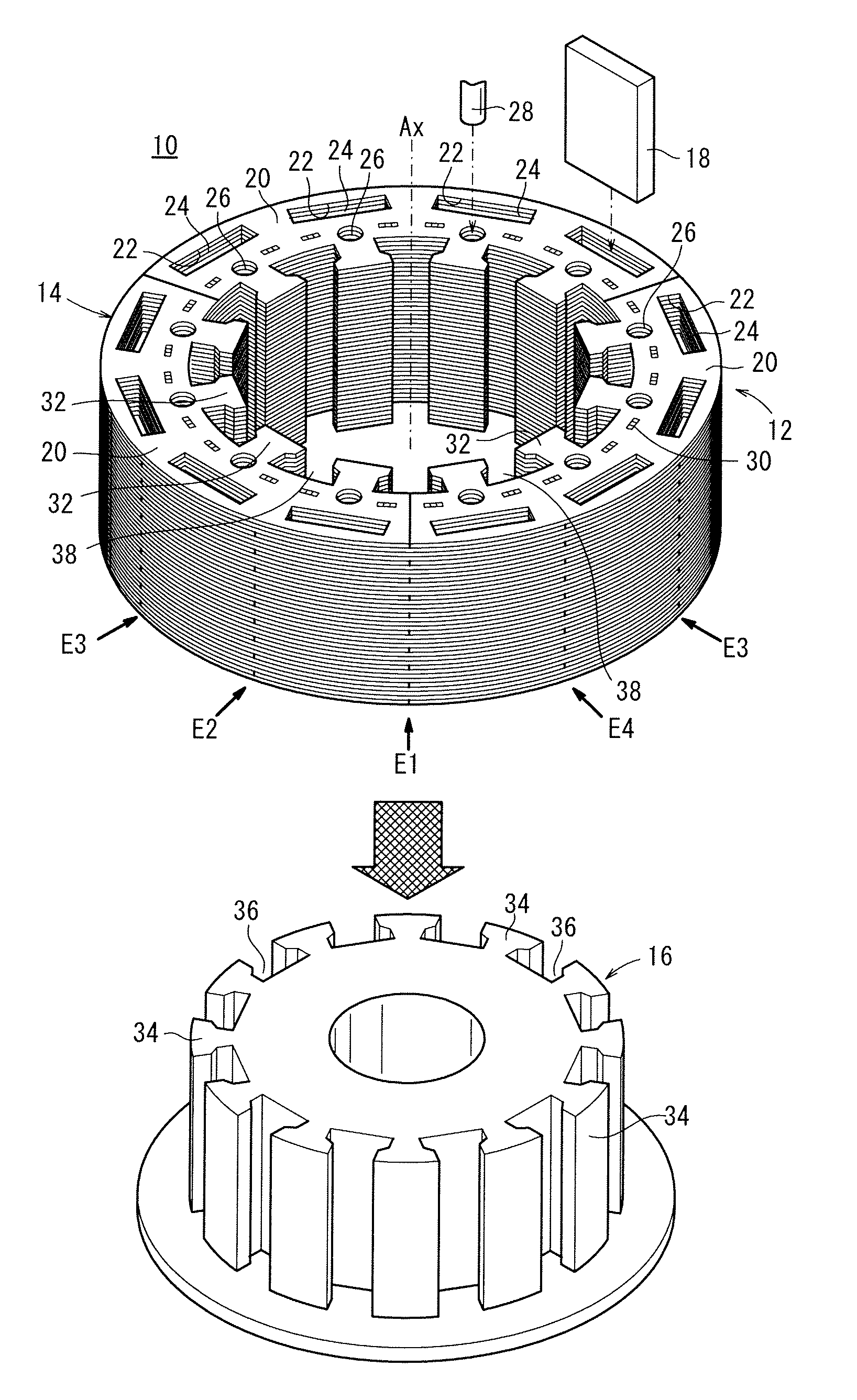
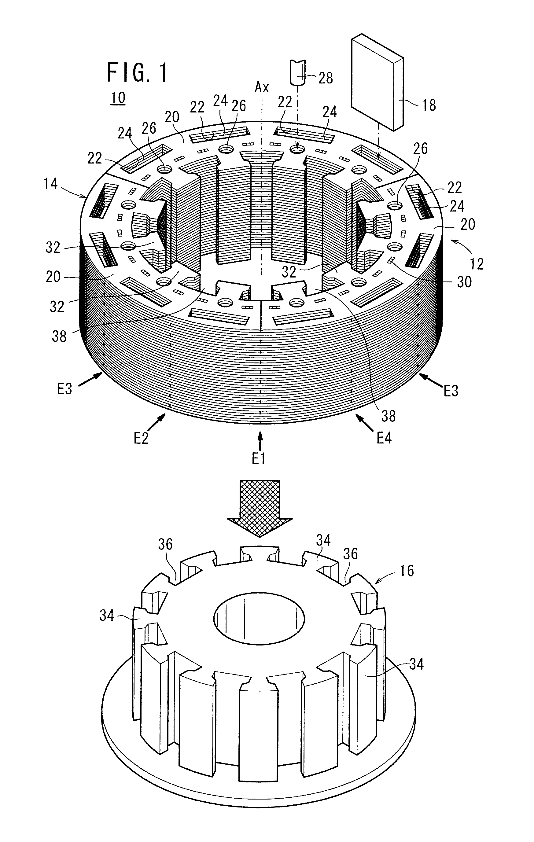
[0033]FIG. 1 is an exploded perspective view of a rotor 10 as a rotary electric machine according to an embodiment of the present invention. The rotor 10 according to the present embodiment cooperates with a stator, etc., not shown, in making up an electric motor.

[0034]The rotor 10 includes a rotor core 12 (ring core) made up of a plurality of (e.g., one hundred sheets of) stacked ring-shaped core plates 14, a shaft 16 inserted through the rotor core 12, and a plurality of magnets 18 inserted in the rotor core 12. The shaft 16 according to the present embodiment has a higher coefficient of thermal expansion than each of the ring-shaped core plates 14.

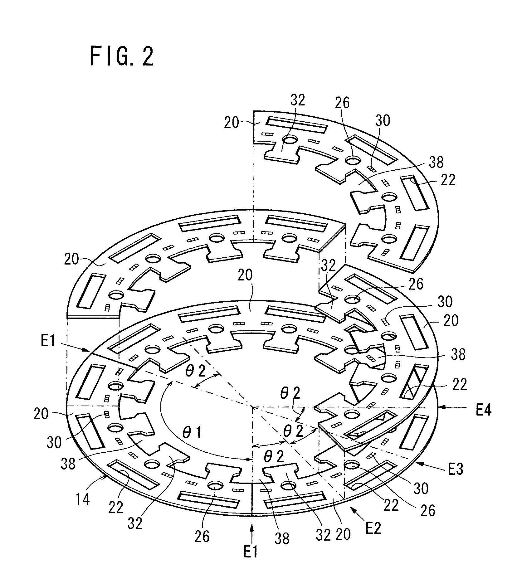
[0035]Each of the ring-shaped core plates 14 comprises a predetermined number (3 in the present embodiment) of thin, sectorial divided core plates 20 arranged circumferentially into a ring shape. If it is assumed that the position where two divided core plates 20 of the ring-shaped core plate 14 in the lower...


PUM

PropertyMeasurementUnit
angleaaaaaaaaaa
angleaaaaaaaaaa
angleaaaaaaaaaa

Abstract

Provided are a rotating electrical machine and a method for manufacturing the rotating electrical machine, wherein the tapered surface of a plate-side tapered section and the tapered surface of a shaft-side tapered section are bonded with pressure by having forces operate between a plurality of plate-side protruding sections and a plurality of shaft-side protruding sections in the directions wherein the plate-side protruding sections and the shaft-side protruding sections are separated from each other. Thus, a ring core is fixed to a shaft.

Description

TECHNICAL FIELD[0001]The present invention relates to a rotary electric machine including a ring core made up of a plurality of stacked ring-shaped core plates each comprising a plurality of divided core plates, a shaft inserted through the ring core, and a plurality of magnets inserted in magnet insertion holes defined in the divided core plates.BACKGROUND ART[0002]There are known rotary electric machines for use as parts in electric motors or the like. The rotary electric machines mainly include a ring core made up of a plurality of stacked ring-shaped core plates, a shaft inserted through the ring core, and a plurality of magnets disposed in the ring core. Known technologies for fitting the ring core over the shaft include a shrink-fitting process and a press-fitting process (for example, Japanese Laid-Open Patent Publication No. 07-022168). According to Japanese Laid-Open Patent Publication No. 07-022168, a hollow cylindrical rotor (1) is heated to increase its inside diameter, ...

Claims


Application Information

Patent Timeline
Patent Type & Authority Applications(United States)
IPC IPC(8): H02K1/30H02K15/02
CPCH02K1/276H02K15/03Y10T29/49012H02K1/30
Inventor SAITO, MASAFUMIMATSUO, YASUTAKASHIGEMATSU, HIDEKITANAKA, TOSHIYUKIAKUTSU, KUNIAKI
Owner HONDA MOTOR CO LTD
Why Eureka
Try Eureka