Rotation support of heat-dissipation fan

a technology of rotation support and heat dissipation fan, which is applied in the direction of propellers, propulsive elements, water-acting propulsive elements, etc., can solve the problems of fan instability, abnormal heat and loud noise, and generating vibration, so as to reduce surface contact area, reduce friction, and high speed rotation

Inactive Publication Date: 2005-05-17
SUNG KUAN KUAN +1
View PDF4 Cites 20 Cited by
  • Summary
  • Abstract
  • Description
  • Claims
  • Application Information

AI Technical Summary

Benefits of technology

[0006]In order to achieve these objectives, the present invention provides an improved structure comprising a hollow ceramic bearing passing through and affixed to the fan rotor and rotating with it, and a hollow or solid ceramic tube passing through the inside of the bearing and rotating freely to reduce friction and allow for high speed rotation. The exterior surface of the bearing and the exterior of the axle tube are processed to reduce surface contact area between them, thereby further reducing rotational friction.
[0007]The present invention comprises a ceramic hollow tubular bearing, support bearing and axle tube, and a ceramic holding ring. The bearing passes through and is fixedly attached to the fan rotor and rotates with the rotor. The support bearing is fixedly attached to the fan base, acting as structural support, and does not rotate. The axle tube is either cylindrical in shape or contains an end flange portion, forming a T-shaped (in cross-section) tube. The axle tube passes through the inside of the bearing and support bearing, and rotates asynchronously and freely with the fan rotor. The axle tube functions as structural support, providing multi-point contact with the rotating support mechanism. The ceramic holding ring has an opening or gap and is installed at one end of the axle to tube to limit axial movement of the axle tube.
[0008]When the heat-dissipation fan is energized and rotating, the bearing rotates with the rotor. The axle tube is then carried forward asynchronously and incrementally, thereby rotating slowly within the bearing. Since the bearing and axle tube are rotating at different speeds in the same direction, friction is reduced and fan speed and efficiency are increased. To avoid movement of the axle tube in the axial direction, a ceramic holding ring (a C-ring) is installed at the end of the axle tube furthest from the fan rotor. The rotating bearing, fixed support bearing, free-moving axle tube and auto balancing of magnetic forces combine to create a very stable high speed rotating support mechanism with multipoint contact, delivering minimum vibration and friction.
[0009]The bearing and support bearing are hollow ceramic tubes, the exteriors of which are ground or otherwise formed with a concave surface or a grooved shape, to provide a simple but solid connection with the fan rotor body, suitable for mass production of injection molded fan rotor bodies. The interior of the bearing and support bearing are ground or otherwise formed with concave grooves to further reduce surface contact and friction among the bearing, support bearing and axle tube.
[0010]The axle tube is a solid or hollow ceramic tube with a cylindrical shape, or with an end flange portion forming a T-shape (in cross-section). The exterior of the axle tube is ground or otherwise formed with concave grooves or with a non-circular shape to further reduce surface contact and friction among bearing, support bearing and axle tube.
[0011]In addition, the gap between bearing / support bearing and axle tube is kept below ten microns in width to prevent vibration and noise.

Problems solved by technology

Ball bearing 103 has a lower coefficient of friction and longer life than metal sleeve 104, but when dust or debris enters ball bearing 103, resulting bearing friction rapidly causes it to deteriorate; generating vibration, abnormal heat and loud noise.
Eventually the fan will become unstable.
In addition, the price of a ball bearing is higher than that of alternative bearing structures.
Metal sleeve 104 is cheap, but wears out very quickly, requiring regular maintenance and replacement.
In the conventional art, when lubricant is consumed, abnormal heat and friction will greatly shorten the life of the fan.
This results in high heat, high friction, reduced rotor speed and wasting of energy.

Method used


Image

  • Rotation support of heat-dissipation fan
  • Rotation support of heat-dissipation fan
  • Rotation support of heat-dissipation fan

Examples


Embodiment Construction

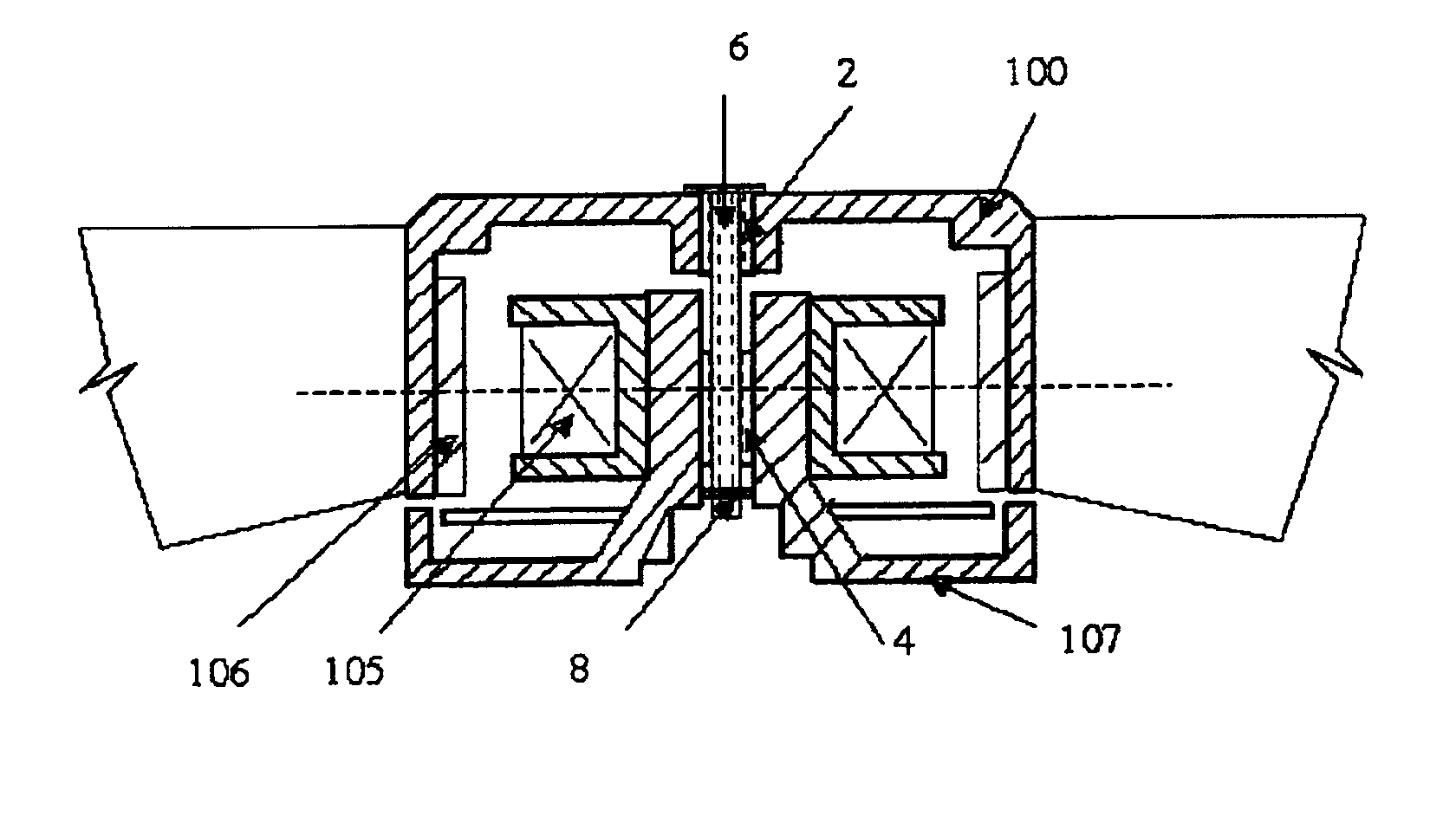
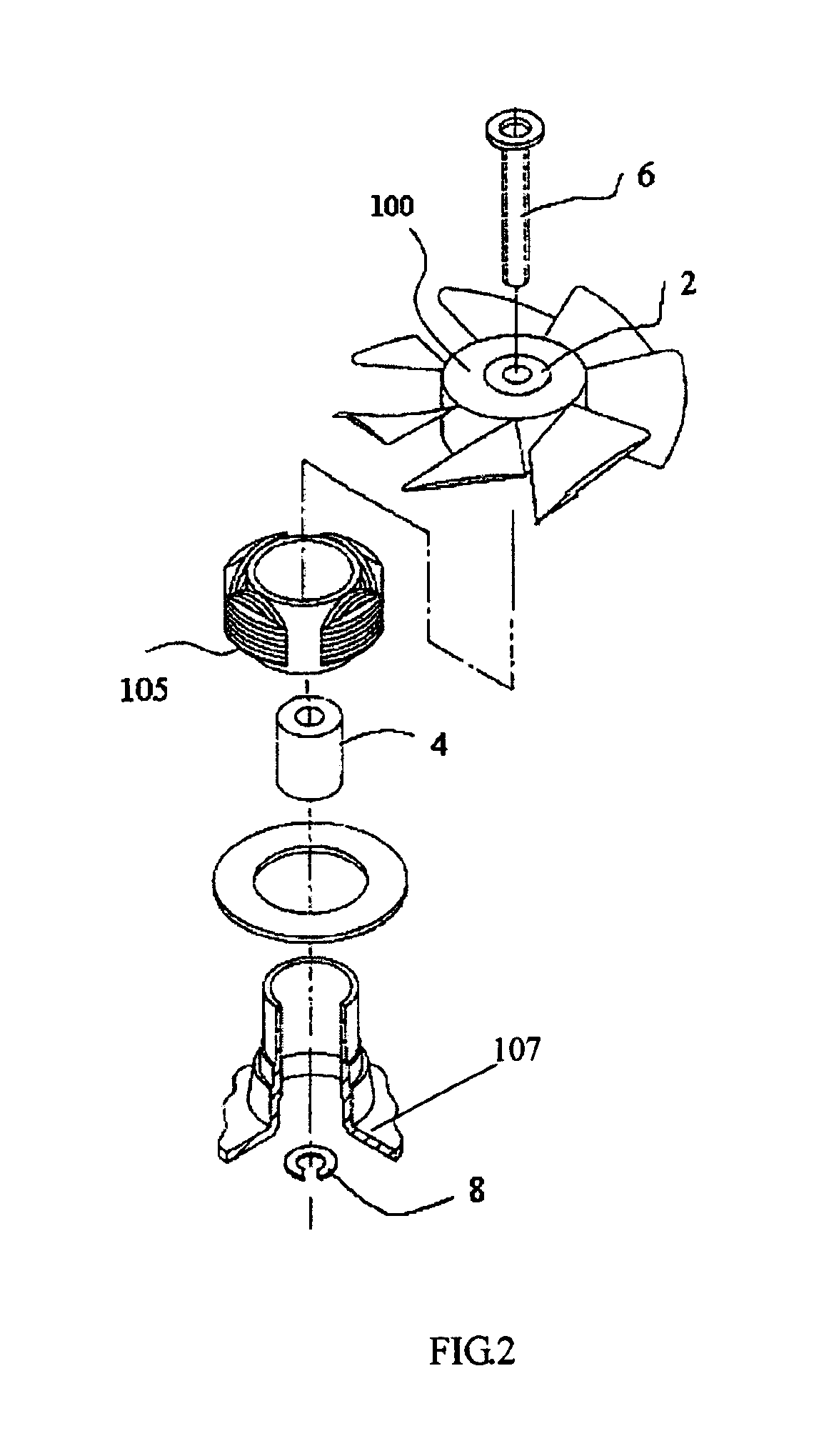
[0020]FIG. 2 shows an exploded view of the present invention. Hollow ceramic tube bearing 2 passes through and is concentrically and fixedly attached to fan rotor 100, thereby rotating with the rotor. Hollow ceramic tubular support bearing 4 is fixedly mounted onto fan base 107. Axle tube 6 is cylindrical in shape, or with an end flange portion, forming a T-shaped (in cross-section) tube, which passes through the inside of bearing 2 and support bearing 4, and rotates slowly and asynchronously with rotor 100. Ceramic holding ring 8 has an opening or gap, and is installed at the end of axle tube 6, opposite rotor 100, to limit axial movement of axle tube 6.

[0021]When the fan is energized and rotating, bearing 2 rotates with rotor 100, and axle tube 6 is carried forward asynchronously, thereby rotating slowly within bearing 2 and support bearing 4. Since bearing 2 and axle tube 6 are rotating at different speeds in the same direction, this will greatly reduce friction and increase fan ...


PUM


Abstract

An improved structure for rotational support for a heat-dissipation fan is disclosed, comprising a hollow ceramic bearing passing through and concentric with the fan rotor and rotating with said rotor, a hollow ceramic support bearing fixedly mounted to the base of the fan, and a hollow or solid ceramic axle tube passing through the inside of said bearing and rotating freely to reduce friction and allow high-speed rotation. The exterior surface of said bearing is ground or otherwise formed to provide better connection with the rotor, while the interior of the bearing and exterior of the axle tube are further processed to reduce contact area therebetween to reduce rotation friction. This improved structure has achieved reduced friction, reduced noise, reduced power consumption, longer life and higher rotational speed.

Description

BACKGROUND OF THE INVENTION[0001]The present invention relates to an improved structure for rotational support of a heat-dissipation fan, wherein a ceramic bearing is fixed onto a rotor and rotates with it. Various ceramic axle tube supporting structures are provided, and interior and exterior surfaces of the bearing and axle tube are further processed to reduce rotational friction between them, reduce noise, reduce power consumption, and achieve longer life and allow higher rotational speed.[0002]FIG. 1 is an exploded view of a heat-dissipation fan according to the prior art. Axial shaft 101 is fixedly attached to rotor 100 at one end and surrounded by axle tube 102, supported by either ball bearing 103 or metal sleeve 104. When stator coil 105 is energized to generate impelling magnetic force, the circular permanent magnet installed inside rotor 100 acts upon this magnetic force and rotates the motor. The ball bearing 103 or metal sleeve 104 is a key component of fan rotation in t...

Claims


Application Information

Patent Timeline
Patent Type & Authority Patents(United States)
IPC IPC(8): F04D29/04F04D29/056F04D29/057
CPCF04D29/057F04D29/0566
Inventor SUNG, KUAN KUANCHENG, EDWARD
Owner SUNG KUAN KUAN
Why Eureka
Try Eureka