Circuit for controlling power output from battery pack and battery pack

A technology for battery packs and electric power, which is applied in the direction of battery disconnection circuit, battery circuit device, secondary battery charging/discharging, etc., and can solve problems such as failure to prevent battery burnout

Active Publication Date: 2018-07-13
SAMSUNG ELECTRONICS CO LTD
View PDF4 Cites 2 Cited by
  • Summary
  • Abstract
  • Description
  • Claims
  • Application Information

AI Technical Summary

Problems solved by technology

However, even the above operations ca

Method used


Image

  • Circuit for controlling power output from battery pack and battery pack
  • Circuit for controlling power output from battery pack and battery pack
  • Circuit for controlling power output from battery pack and battery pack

Examples


Embodiment Construction

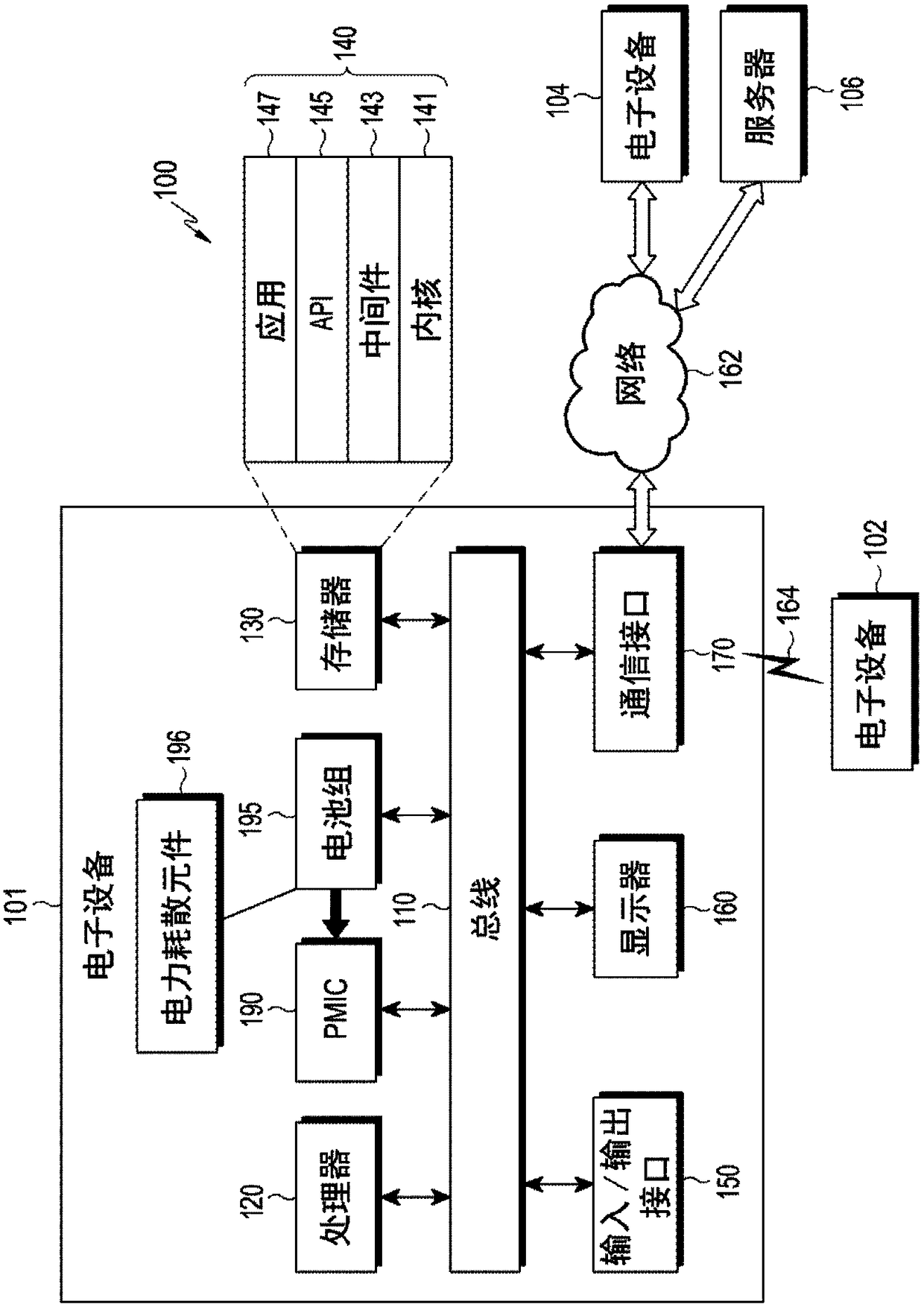
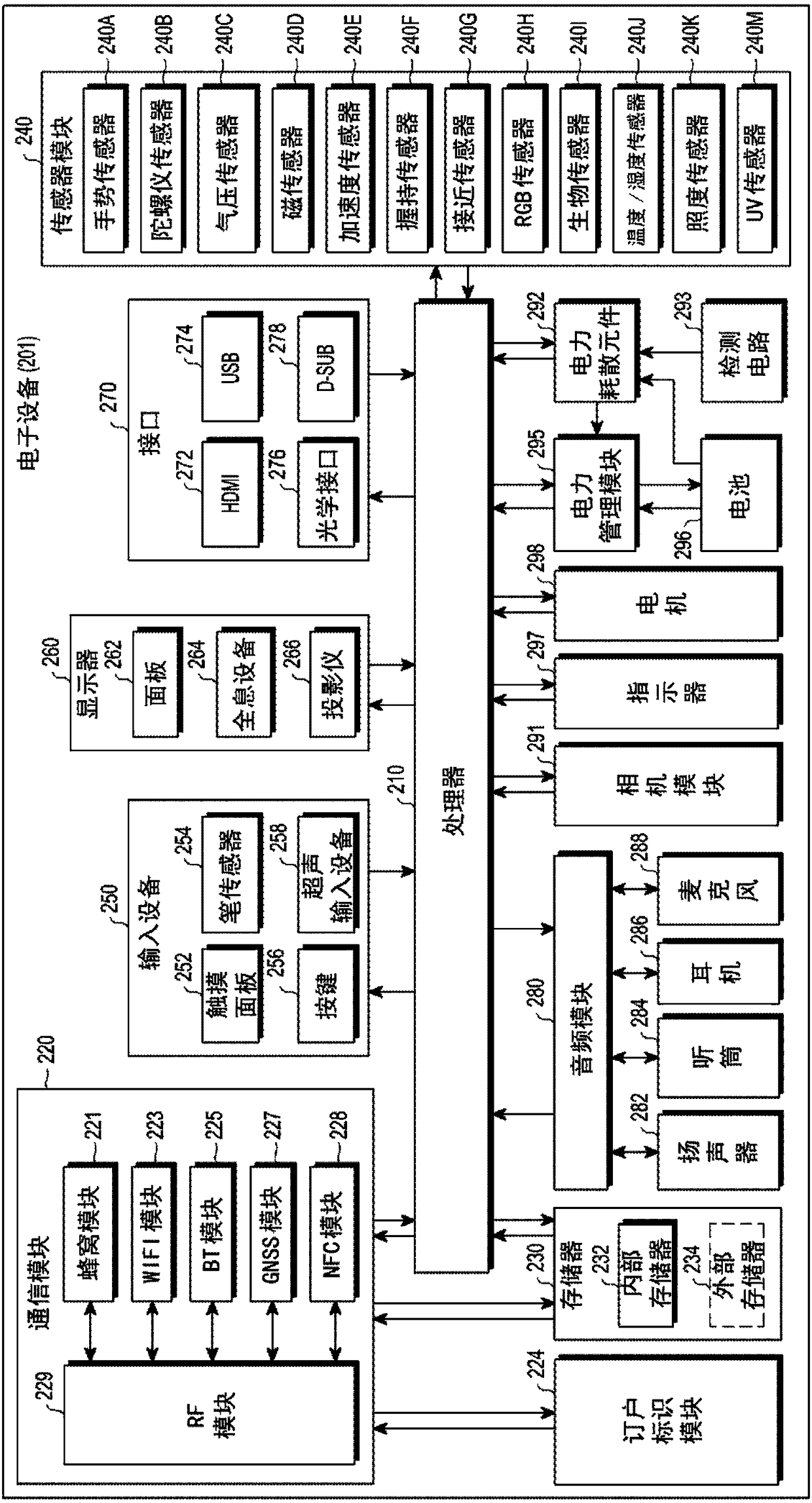
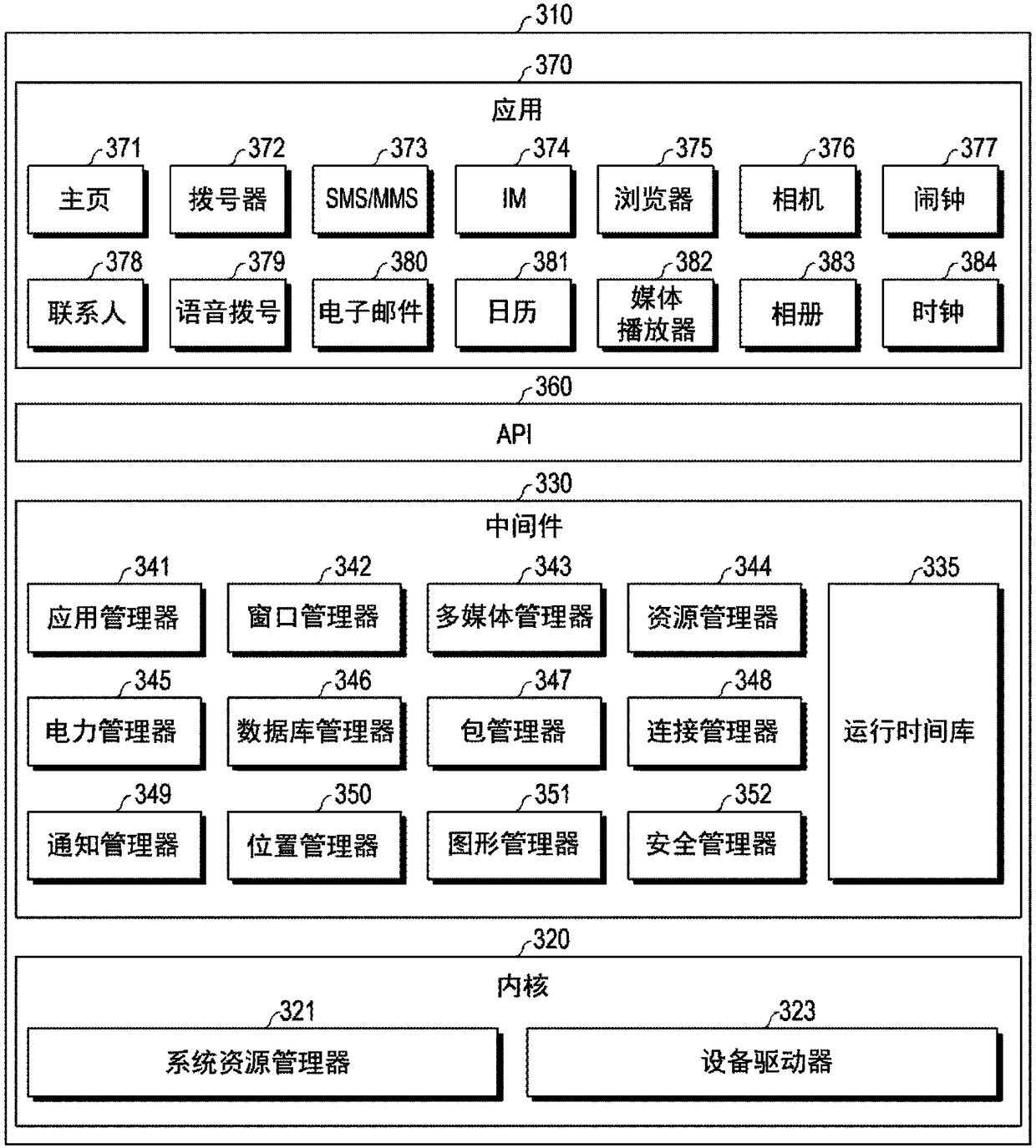
[0030] Hereinafter, various exemplary embodiments of the present disclosure will be described with reference to the accompanying drawings. Example embodiments and terms used herein are not intended to limit the technology disclosed herein to a specific form, and should be understood to include various modifications, equivalents, and / or alternatives of the corresponding embodiments. In describing the drawings, like reference numerals may be used to designate like constituent elements. A singular expression may include a plural expression unless they are clearly different in context. As used herein, a singular form may include a plural form unless the context clearly dictates otherwise. The expression "first" or "second" used in various embodiments of the present disclosure may modify various components regardless of order and / or importance, but does not limit the corresponding components. When an element (eg, a first element) is referred to as being "connected (functionally o...


PUM


Abstract

A portable communication device, according to various embodiments of the present disclosure, may include: a battery pack; a power dissipation element disposed outside the battery pack; a detecting circuit configured to detect the state of the battery pack; and at least one of first switches that are connected to the battery pack and the detecting circuit, wherein the detecting circuit is configured to control at least one of the first switches to: electrically disconnect the power dissipation element from the battery pack when the state of the battery pack does not satisfy a specified condition; and electrically connect the power dissipation element to the battery pack when the state of the battery pack satisfies the specified condition.

Description

technical field [0001] The present disclosure generally relates to a circuit for controlling power output from a battery pack, and also relates to a battery pack. Background technique [0002] A battery cell may include a positive electrode, a negative electrode, an electrolyte, and a separator, and may perform charge and discharge operations by movement of lithium ions between the positive electrode and the negative electrode. The separator is used to separate the positive electrode and the negative electrode from each other, and is used for movement of lithium ions. In the case of lithium batteries, the state of lithium ions can differ between positive and negative electrodes. Due to the different states, a potential difference can occur between the positive and negative electrodes, allowing electrons to move and thus carry out the discharge process. Thus, for example, current can flow from the aluminum foil of the positive electrode collector plate to the copper foil of...

Claims


Application Information

Patent Timeline
IPC IPC(8): H02J7/00
CPCH02J7/0029H02J7/0063H02J7/00719H02J7/00304H02J7/00309H02J7/007182H02J7/00714H02J7/007194H02J7/00308H01M10/48H02J7/0031Y02E60/10G01R31/382H01M10/425H01M10/448H01M2010/4271H01M50/569H01M10/44H02J7/0044H01M2220/30
Inventor 李勇承金斗贤金炫锡林浩永郑秉相
Owner SAMSUNG ELECTRONICS CO LTD
Why Eureka
Try Eureka