Gantry robot moving mechanism directly driven by frameless permanent-magnet synchronous motor

A technology of permanent magnet synchronous motor and moving mechanism, which is applied to electric components, magnetic circuit rotating parts, magnetic circuit shape/pattern/structure, etc., can solve the problem of increasing difficulty in design, manufacturing and assembly, transmission efficiency and accuracy Large losses, increased transmission parts, etc., to achieve the effect of improving driving efficiency, fast response speed, and reducing volume

Pending Publication Date: 2018-07-13
HUBEI HUANYEE ELECTROMAGNETIC EQUIP ENG TECH CO LTD
View PDF6 Cites 0 Cited by
  • Summary
  • Abstract
  • Description
  • Claims
  • Application Information

AI Technical Summary

Problems solved by technology

[0003] At present, there are more and more types of gantry robots, their functions are becoming more and more perfect, and their structures are becoming more and more complex. However, their moving mechanisms are generally composed of motors, belts, gears, connecting rods and other transmission devices. The intermediate links of transmission are relatively complex. More, the efficiency and accuracy of the transmission are greatly lost, and at the same time, due to the increase in the number of transmission components, the performance is affected, which also leads to more difficulty in design, manufacture and assembly, and an increase in cost

Method used


Image

  • Gantry robot moving mechanism directly driven by frameless permanent-magnet synchronous motor
  • Gantry robot moving mechanism directly driven by frameless permanent-magnet synchronous motor
  • Gantry robot moving mechanism directly driven by frameless permanent-magnet synchronous motor

Examples


Embodiment 1

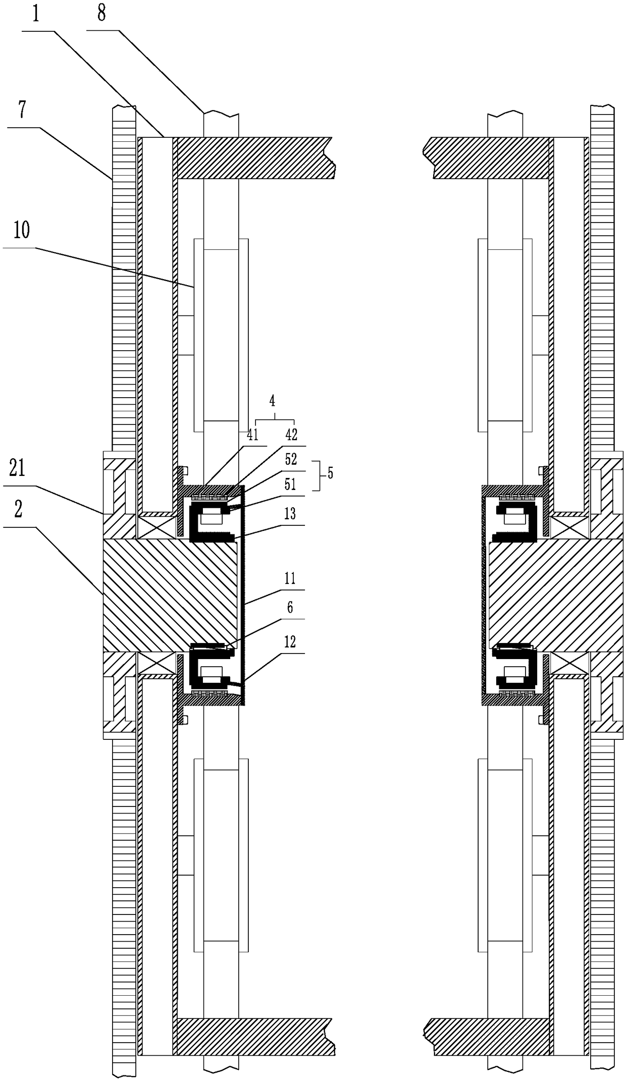
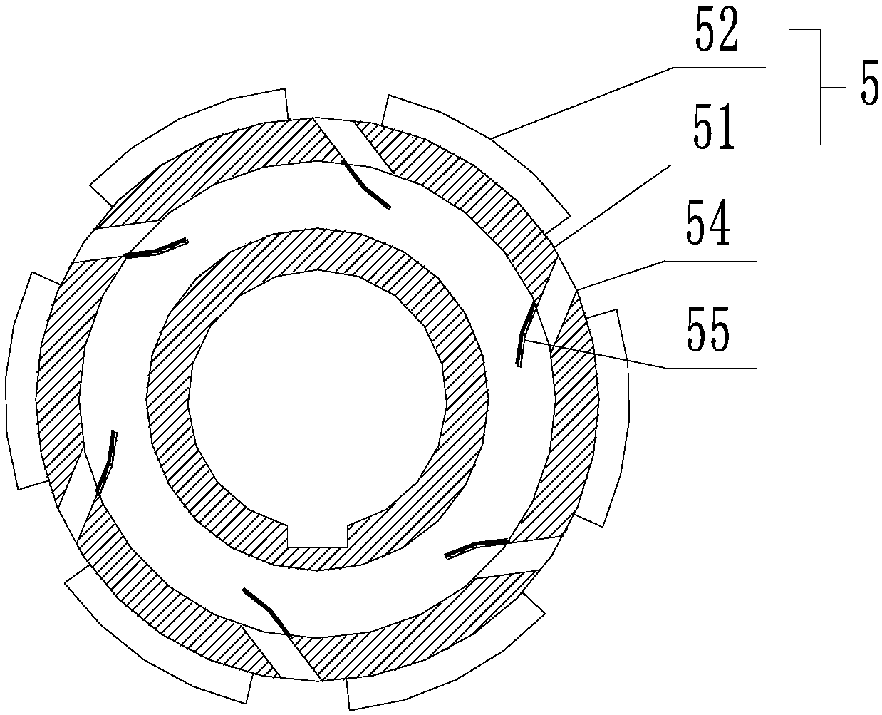
[0031] Such as Figure 1-6 As shown, a frameless permanent magnet synchronous motor direct-driven gantry-type robot moving mechanism, the gantry-type robot moving mechanism includes a track 8 and a rolling wheel 10 adapted to the track 8; the rolling wheel 10 is placed on the body frame 1 of the gantry-type robot moving mechanism; the gantry-type robot moving mechanism moves along the track 8 through the rolling wheels 10; the gantry-type robot moving mechanism also includes a rotating shaft 2, The gear 21 fixed on the end of the rotating shaft 2 and the rack 7 matched with the gear 21; the rack 7 is arranged parallel to the track 8; the rotating shaft 2 is fixedly mounted on the bearing 3 In the body frame 1 of the gantry type robot moving mechanism; the rotating shaft 2 is directly driven by a frameless permanent magnet synchronous motor; the frameless permanent magnet synchronous motor includes a stator assembly 4 and a rotor assembly 5; the stator assembly 4 It is fixedly...

Embodiment 2

[0036] Such as Figure 7-10 As shown, a frameless permanent magnet synchronous motor direct-driven gantry-type robot moving mechanism, the gantry-type robot moving mechanism includes a track 8 and a rolling wheel 10 adapted to the track 8; the rolling wheel 10 is placed on the body frame 1 of the gantry-type robot moving mechanism; the gantry-type robot moving mechanism moves along the track 8 through the rolling wheels 10; the gantry-type robot moving mechanism also includes a rotating shaft 2, The gear 21 fixed on the end of the rotating shaft 2 and the rack 7 matched with the gear 21; the rack 7 is arranged parallel to the track 8; the rotating shaft 2 is fixedly mounted on the bearing 3 In the body frame 1 of the gantry type robot moving mechanism; the rotating shaft 2 is directly driven by a frameless permanent magnet synchronous motor; the frameless permanent magnet synchronous motor includes a stator assembly 4 and a rotor assembly 5; the stator assembly 4 It is fixedl...

Embodiment 3

[0041] Such as Figure 11 As shown, a frameless permanent magnet synchronous motor direct-driven gantry-type robot moving mechanism, the gantry-type robot moving mechanism includes a track 8 and a rolling wheel 10 adapted to the track 8; the rolling wheel 10 is placed on the body frame 1 of the gantry-type robot moving mechanism; the gantry-type robot moving mechanism moves along the track 8 through the rolling wheels 10, and the gantry-type robot moving mechanism also includes a rotating shaft 2, The gear 21 fixed on the end of the rotating shaft 2 and the rack 7 matched with the gear 21; the rack 7 is arranged parallel to the track 8; the rotating shaft 2 is fixedly mounted on the bearing 3 In the body frame 1 of the gantry type robot moving mechanism; the rotating shaft 2 is directly driven by a frameless permanent magnet synchronous motor; the frameless permanent magnet synchronous motor includes a stator assembly 4 and a rotor assembly 5; the stator assembly 4 It is fixe...


PUM


Abstract

Disclosed is a gantry robot moving mechanism directly driven by a frameless permanent-magnet synchronous motor. The gantry robot moving mechanism comprises tracks and rolling wheels matched with the tracks; the rolling wheels are arranged on a rack of a gantry robot moving mechanism body; the gantry robot moving mechanism moves along the tracks through the rolling wheels; the gantry robot moving mechanism further comprises a rotating shaft, a gear fixed at one end of the rotating shaft and a rack matched with the gear; the rack is parallelly arranged with the tracks; the rotating shaft is fixedly mounted in the frame of the gantry robot moving mechanism body through a bearing; the rotating shaft is directly driven through the frameless permanent-magnet synchronous motor. The frameless permanent-magnet synchronous motor is simple in structure, high in driving efficiency and large in torque.

Description

technical field [0001] The invention relates to the field of gantry robots, in particular to a gantry robot moving mechanism directly driven by a frameless permanent magnet synchronous motor. Background technique [0002] The gantry robot is an automatic device that performs work automatically. The gantry robot can assist or replace human work. It is more and more widely used in the fields of industry, medicine, agriculture, construction, military and daily life, and its role is becoming more and more important. Big, bring a lot of convenience to mankind. [0003] At present, there are more and more types of gantry robots, their functions are becoming more and more perfect, and their structures are becoming more and more complex. However, their moving mechanisms are generally composed of motors, belts, gears, connecting rods and other transmission devices. The intermediate links of transmission are relatively complex. More, the efficiency and accuracy of the transmission ar...

Claims


Application Information

Patent Timeline
Patent Type & Authority Applications(China)
IPC IPC(8): H02K29/08H02K1/14H02K1/32H02K1/20H02K5/10H02K9/06
CPCH02K1/145H02K1/20H02K1/32H02K5/10H02K9/06H02K29/08
Inventor 黄诚杨勇强
Owner HUBEI HUANYEE ELECTROMAGNETIC EQUIP ENG TECH CO LTD
Why Eureka
Try Eureka