High-efficiency dust-removing equipment

A dust removal equipment and high-efficiency technology, applied in electrostatic effect separation, dispersed particle filtration, solid separation and other directions, can solve the problems of affecting self-cleaning effect, unbalanced swing strength, etc., and achieve stable connection, cost saving, and shortened interval. Effect

Inactive Publication Date: 2018-07-17
昆山木利机械设计有限公司
View PDF1 Cites 3 Cited by
  • Summary
  • Abstract
  • Description
  • Claims
  • Application Information

AI Technical Summary

Problems solved by technology

However, because only the upper end is connected to the swing device, the overall swing strength is uneven, especially the lower part is weak, which affects the overall self-cleaning effect

Method used


Image

  • High-efficiency dust-removing equipment
  • High-efficiency dust-removing equipment
  • High-efficiency dust-removing equipment

Examples


Embodiment 1

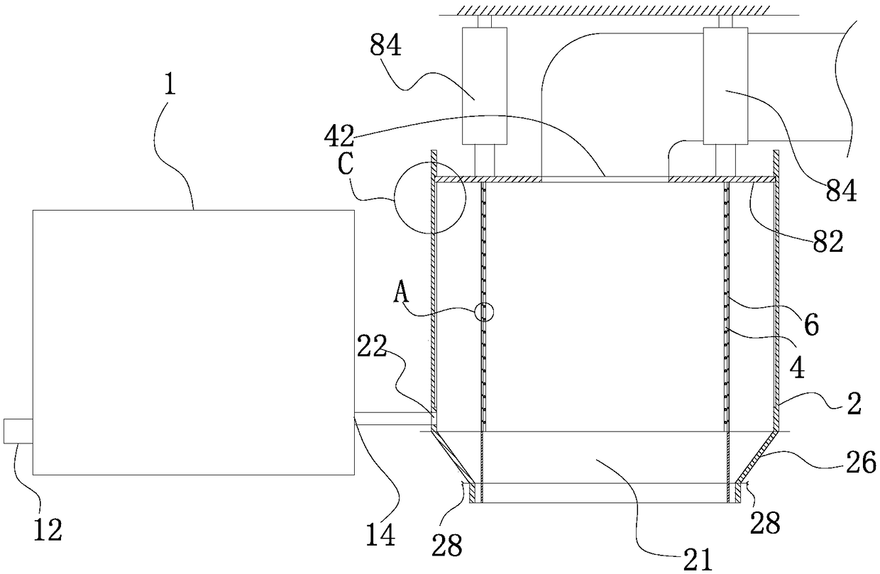
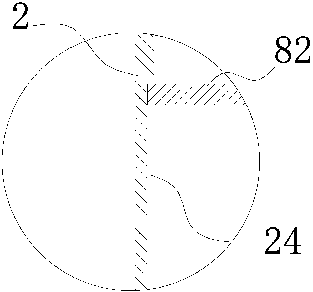
[0050] like Figure 1-5 As shown, a high-efficiency dust removal equipment includes a dust removal cylinder 2, a bag cylinder 4 arranged in the dust removal cylinder 2, an air inlet 22 connected to the dust removal cylinder 2 and an air outlet 42 connected to the bag cylinder 4, and It includes several telescopic brackets 6 arranged on the side of the bag cylinder 4 and capable of driving the bag cylinder 4 to compress or restore as a whole.

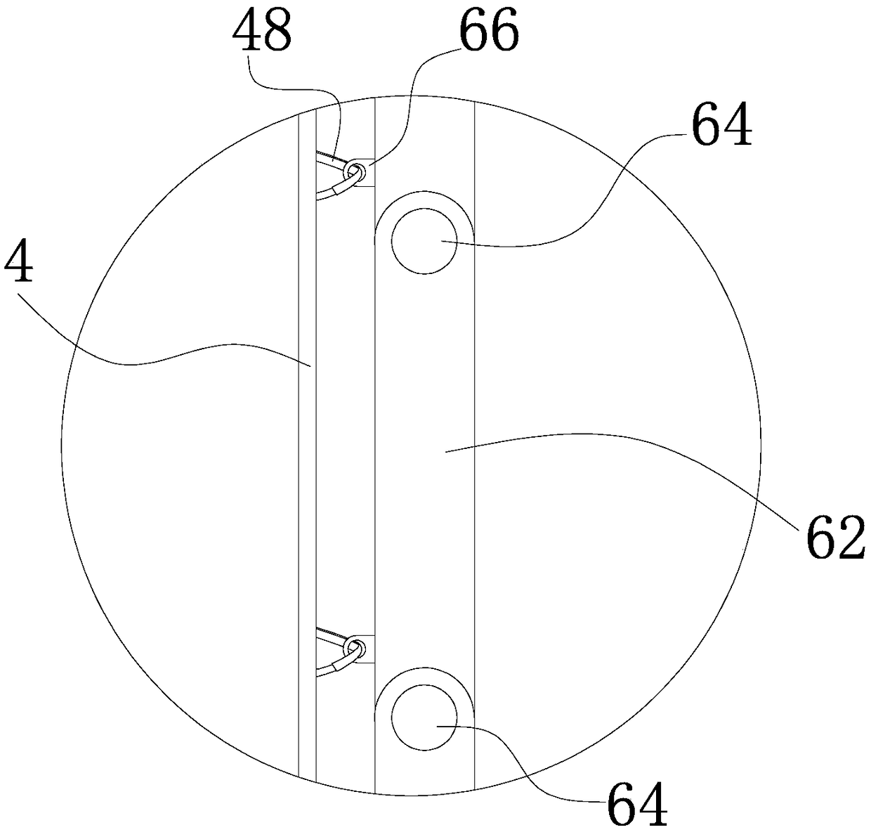
[0051] Specifically, the telescopic support 6 and the bag cylinder 4 are fixed at multiple points at equal intervals in the axial direction. The telescopic bracket 6 is formed by hinged end to end of a plurality of rod-shaped units 62 to form a plurality of hinge points 64 . The bag cylinder 4 has alternate wavy creases with mountain folds and valley folds extending axially, and the distance between adjacent mountain folds and valley folds on the bag cylinder 4 is 1 / 3 of the axial height of the bag cylinder 4 in a straightened state. 4...

Embodiment 2

[0061] like Figure 2-6 As shown, the difference between the high-efficiency dust removal equipment of the present invention and Embodiment 1 is that it includes two sets of dust removal cylinders 2 capable of working independently and corresponding bag cylinders 4, and the first-stage air outlet 14 of the electrostatic precipitator 1 is divided into two The roads are respectively connected to the air inlets 22 of the two dust removal cylinders 2, and the two roads are respectively provided with valves 86 to control on-off.

[0062] During operation, the flue gas to be treated still enters from the primary air inlet 12, and after being treated by the electrostatic precipitator 1, it enters the two dust removal cylinders 2 through the corresponding air inlets 22 for further filtration. In each dust removal cylinder 2, the flue gas enters the interior from the outside of the bag cylinder 4, and then is discharged upward through the air outlet 42 to complete the entire dust remov...


PUM


Abstract

The invention discloses high-efficiency dust-removing equipment. The equipment comprises a dust removing cylinder body, a cloth bag cylinder body arranged in the dust removing cylinder body, an air inlet communicating with the dust removing cylinder body and an air outlet communicating with the cloth bag cylinder body; and the equipment further comprises a plurality of telescopic supports which are arranged at the side parts of the cloth bag cylinder body and can drive the cloth bag cylinder body to be integrally compressed or restored. The high-efficiency dust-removing equipment provided by the invention uses a cylindrical cloth bag with a simple structure as a filter material, and is particularly provided with the plurality of telescopic supports capable of driving the cloth bag cylinderbody to be integrally compressed or restored at the side parts of the cloth bag cylinder body, so that repeated compression or restoration of the whole cloth bag can be realized as long as pressure or tension is applied to the plurality of telescopic supports; and the effect of high-efficiency vibration dust removal is achieved, service life of a single cloth bag is prolonged, interval time for replacing the cloth bag is greatly shortened, costs are reduced, and therefore dust removing efficiency of the dust-removing equipment is improved on a whole.

Description

technical field [0001] The invention relates to a dust removal device. Background technique [0002] For environmental protection and other purposes, dust removal equipment is usually required to control airborne impurities such as dust and particles within a certain space. In the dust removal equipment, the bag filter is the most common, that is, the bag filter material is used to filter the dusty flue gas to achieve the purpose of purification. However, after the filter material is used for a period of time, it will inevitably accumulate certain impurity particles on the surface, resulting in a decrease in the filtering effect, and the high-frequency replacement of the filter material will increase too much use cost, so it is necessary to clean the surface of the filter material in time Self-cleaning device. Chinese patent CN 102430296A discloses a bag filter, which can solve this problem. The upper end of the dust removal bag is connected to the swing device. During th...

Claims


Application Information

Patent Timeline
Patent Type & Authority Applications(China)
IPC IPC(8): B01D46/02B01D46/04B01D46/08B03C3/017
CPCB01D46/02B01D46/0005B01D46/04B01D46/08B03C3/017
Inventor 李科慧
Owner 昆山木利机械设计有限公司
Why Eureka
Try Eureka