

An improved method for driving rollers for hot rolling forming of bearing rings for rail transit
A technology for rail transit and bearing rings, applied in the direction of rolls, metal rolling, metal rolling, etc., can solve the problem of aggravating the geometric depression in the middle part of the bearing ring, so as to improve the metal utilization rate, reduce the cutting allowance, and reduce the The effect of production costs
Active Publication Date: 2019-10-01
WUHAN UNIV OF TECH
View PDF11 Cites 0 Cited by
- Summary
- Abstract
- Description
- Claims
- Application Information
AI Technical Summary
Problems solved by technology
When quenching in quenching oil, the two ends of the bearing ring cannot shrink and become smaller due to the compression support of the press quenching mold, and the middle part of the bearing ring has no support to cool down and shrink, which further aggravates the geometric depression in the middle part of the bearing ring
Method used
View moreImage
Smart ImageViewing Examples

Examples
Embodiment 1
Login to View More PUM
| Property | Measurement | Unit |
|---|---|---|
| depth | aaaaa | aaaaa |
| length | aaaaa | aaaaa |
Abstract
The invention discloses an improved method for a driving roll used for hot rolling moulding of a rail traffic bearing collar. The improved method is characterized in that hot rolling moulding technological parameters of a high-speed train bearing collar piece are determined according to a collar blank structure; the driving roll is adopted for rolling moulding; a concave position and an initial concave amount of a concave part of a hot rolling prefabricated collar piece are determined; the hot rolling prefabricated collar piece is subjected to thermal treatment; the final concave amount at theconcave part of the pressure-quenched high-speed train bearing collar is determined; metal at the concave position is compensated on the premise of unchanging the size of the metal by changing the structure of the driving roll; and therefore the aim that no concave parts exist at the central part of the hot-rolling moulded-thermally-treated high-speed train bearing collar is realized. By adoptingthe improved method, the condition that the concave part is eradicated in a cutting mode is avoided; the utilization rate of metal is improved; machining time is reduced; and production cost of the collar piece is lowered.
Description
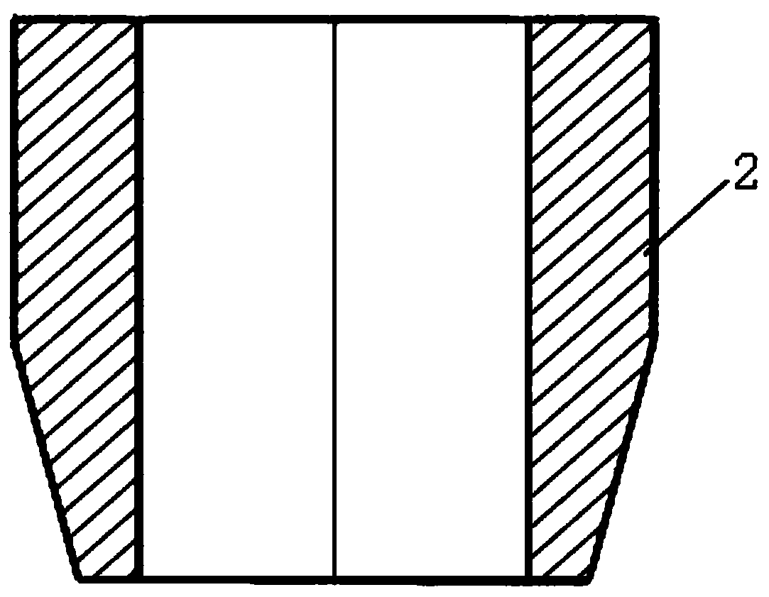
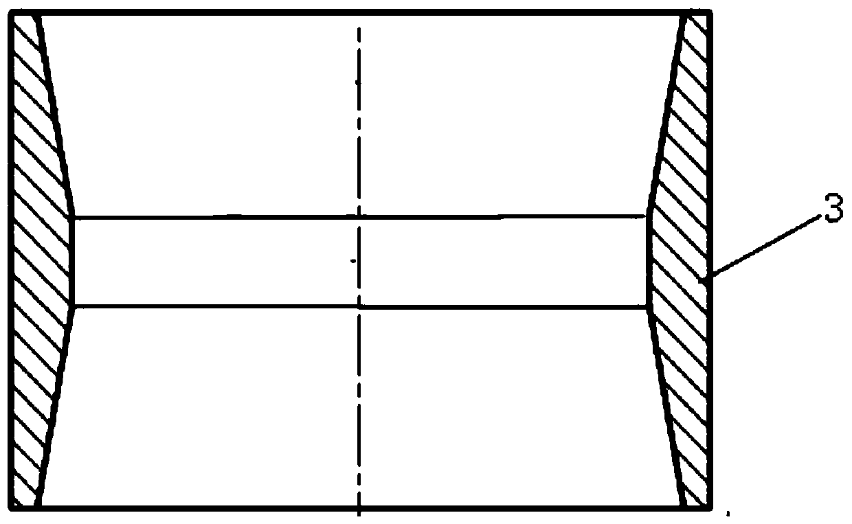
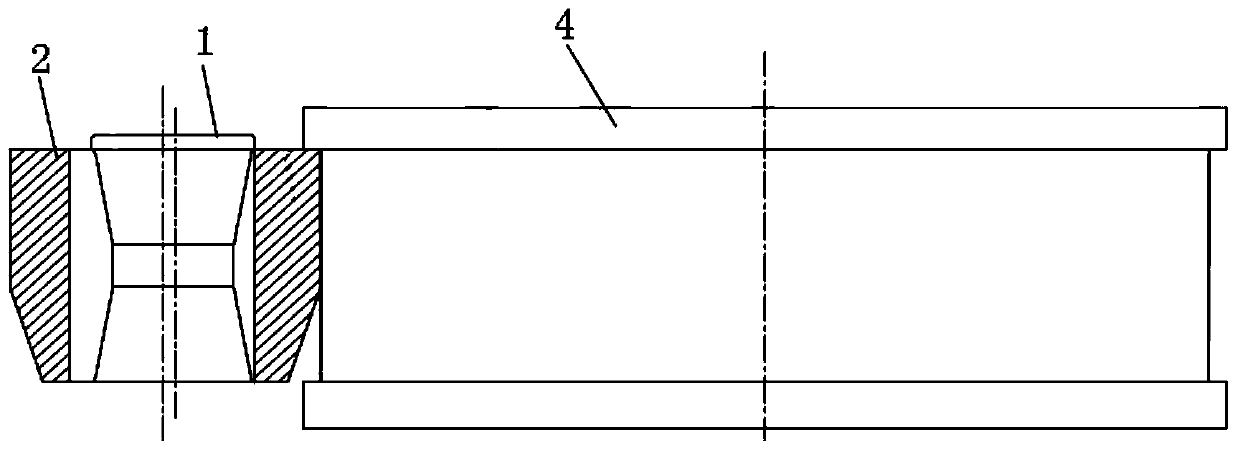
technical field The invention belongs to the technical field of rolling forming of rail transit bearing rings, and in particular relates to an improved method for driving rollers used for hot rolling forming of rail transit bearing rings. Background technique At present, the bearing ring blank with a taper at one end (as shown in Figure 1) is generally used in rail transit to manufacture bearing ring forgings (as shown in Figure 2) by hot rolling, and a large gap is formed between the bearing ring blank structure and the core roll Cavity (as shown in Figure 3), the forging force at both ends of the rail transit bearing ring billet during hot rolling is greater than that of the middle metal, the metal at both ends of the bearing ring has a large plastic deformation, and the middle plastic deformation is small, so the bearing ring A depression is easily formed in the middle, as shown in Figure 4. In the heat treatment process of the bearing ring (carburizing and quenching-sec...
Claims
Login to View More Application Information
Patent Timeline
 Patent Type & AuthorityPatents(China)
IPC IPC(8): B21H1/06B21B27/02C21D1/18
Inventor邓松华林钱东升路小辉魏鹏
OwnerWUHAN UNIV OF TECH