Micro-nano bubble water generating apparatus and water use terminal
What is AI technical title?
AI technical title is built by PatSnap AI team. It summarizes the technical point description of the patent document.
A technology of micro-nano bubbles and generating devices, which is applied in water/sludge/sewage treatment, water aeration, sustainable biological treatment, etc., can solve the problems of reducing water flow velocity and inability to generate micro-nano-scale bubble water, etc., to achieve improved effect of concentration
Pending Publication Date: 2018-07-17
WUHU MIDEA KITCHEN & BATH APPLIANCES MFG CO LTD +1
View PDF7 Cites 2 Cited by
Summary
Abstract
Description
Claims
Application Information
AI Technical Summary
This helps you quickly interpret patents by identifying the three key elements:
Problems solved by technology
Method used
Benefits of technology
Problems solved by technology
[0002] At present, the main function of the existing bubblers in the industry is to reduce the water flow velocity, which can only produce a small amount of large bubbles above the centimeter level, and cannot produce micro-nano bubble water.
Method used
Image
Click on the blue label to locate the original text in one second.
Reading with bidirectional positioning of images and text.
Examples
Embodiment 1
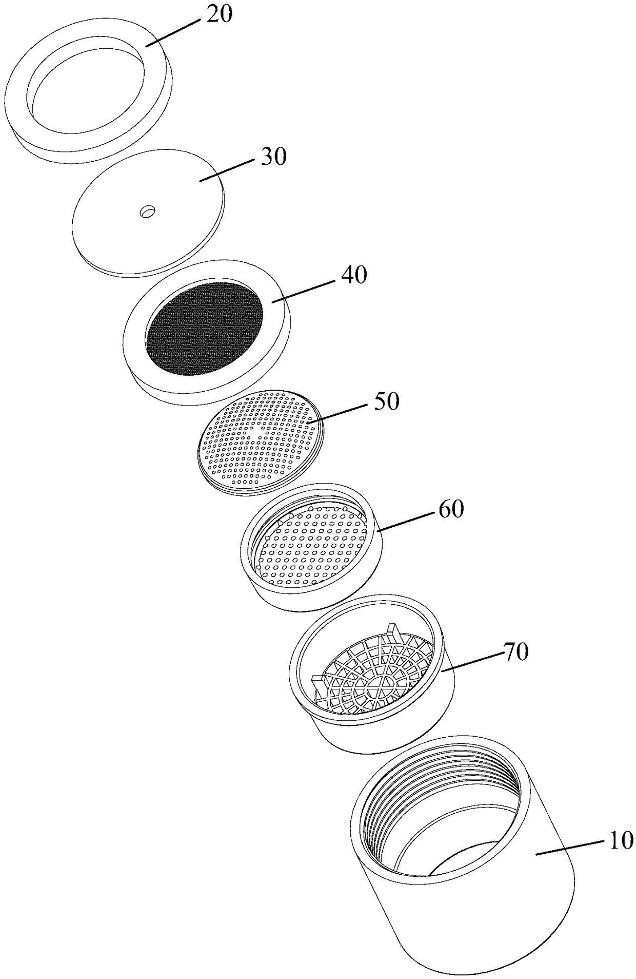
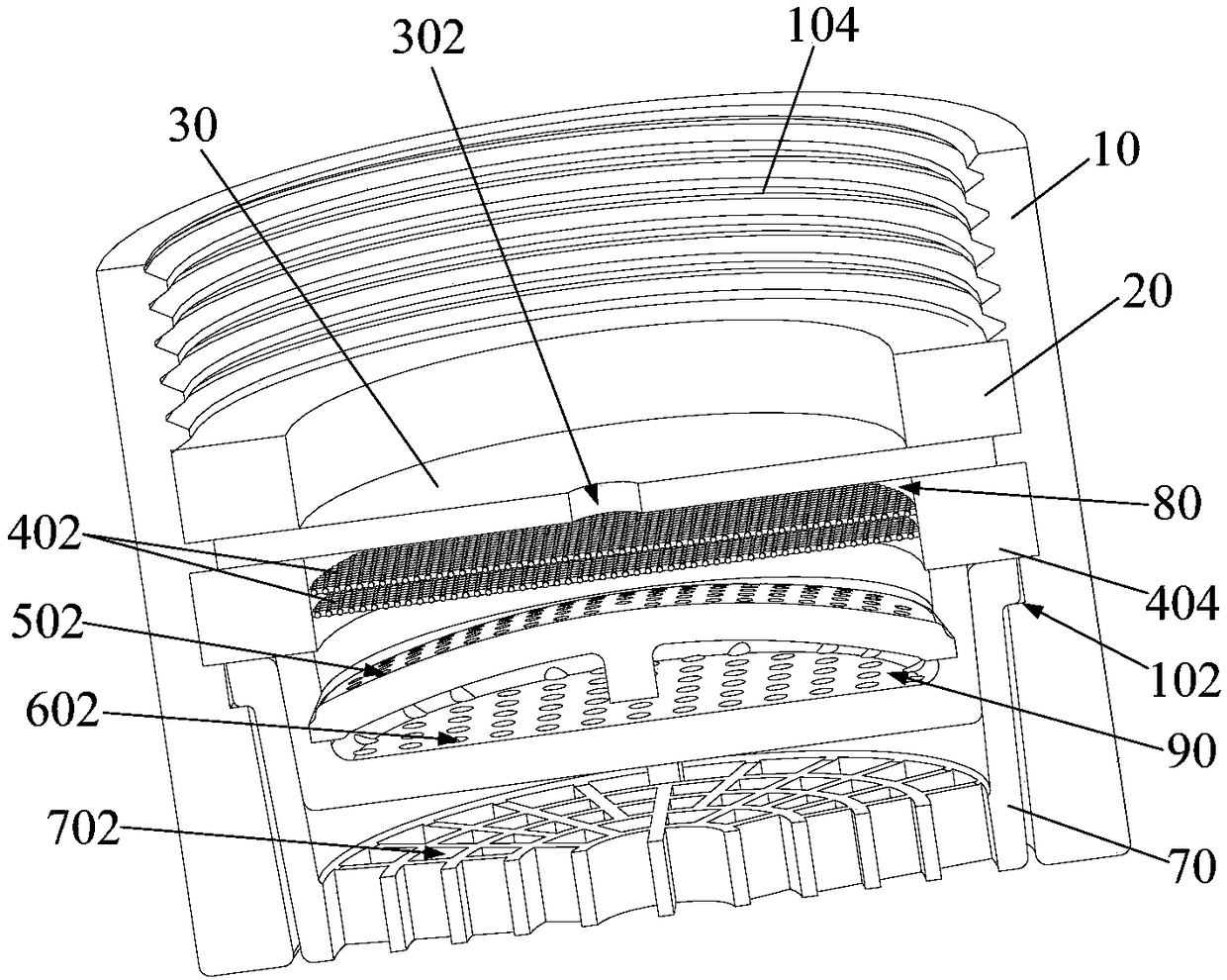
[0069] The flow limiting device comprises a flow limiting sheet 30, and the flow limiting hole 302 is opened on the flow limiting sheet 30, such as figure 1 and figure 2 shown.
[0070] Wherein, the number of flow limiting holes 302 is one, and one flow limiting hole 302 is located in the middle of the flow limiting sheet 30, such as figure 1 and figure 2 shown.
[0071] The current limiting device includes a current limiting plate 30, and a current limiting hole 302 is provided on the current limiting plate 30, which effectively simplifies the structure of the current limiting device, reduces the size of the current limiting device, not only ensures the current limiting effect, but also facilitates processing and molding and assembly.
[0072] When the number of the restrictor hole 302 is one, it is preferably arranged in the middle of the restrictor 30, which is conducive to the force balance of the restrictor 30, so as to avoid the situation that the restrictor 30 til...
Embodiment 2
[0110] Embodiment 2 (not shown in the figure)
[0111] The difference from Embodiment 1 is that: there are multiple flow-restricting holes 302 , and the flow-restricting holes 302 are evenly distributed.
[0112] As for the specific number of restricting holes 302, it is not limited, and may be two, three, four or more. Among them, a plurality of flow-limiting holes 302 are evenly distributed on the current-limiting sheet 30, which is conducive to the force balance of the current-limiting sheet 30, so as to avoid the occurrence of tilting, shifting or even falling off of the current-limiting sheet 30, thereby improving the micro-nano The use reliability of the sparkling water generating device.
Embodiment 3
[0114] The difference from Embodiment 1 is that there is only one filter screen 402 .
PUM
Abstract
The invention provides micro-nano bubble water generating apparatus and a water use terminal. The generating apparatus comprises a shell, a current limiting device and a foaming device; the shell is provided with a water inlet end and a water outlet end; the current limiting device is arranged in the shell and is provided with a current limiting hole; the foaming device is arranged in the shell and is positioned between the current limiting device and the water outlet end of the shell; the foaming device comprises a filter screen which is arranged oppositely to the current limiting device; anda first micro-nano bubble water generating cavity used for forming micro-nano bubble water is defined between the filter screen and the current limiting device. According to the micro-nano bubble water generating apparatus provided by the invention, the first micro-nano bubble water generating cavity is formed between the current limiting device and the filter screen through the arrangement of the current limiting device and the filter screen; pressure is reduced when high-pressure water containing dissolved gas and entering the shell enters the cavity through the current limiting hole, so that micro-nano bubbles are generated; and the filter screen forms a first layer of obstacle to enable the mixture of the micro-nano bubbles and water to flow at a reduced speed, so that the uniform micro-nano bubble water is formed.
Description
technical field [0001] The invention relates to the technical field of water treatment equipment, in particular to a micro-nano bubble water generating device and a water use terminal including the micro-nano bubble water generating device. Background technique [0002] At present, the main function of the existing bubblers in the industry is to reduce the water flow velocity, which can only produce a small amount of large bubbles above the centimeter level, and cannot produce micro-nano bubble water. Contents of the invention [0003] In order to solve at least one of the above technical problems, an object of the present invention is to provide a micro-nano-bubble water generating device. [0004] Another object of the present invention is to provide a water terminal comprising the above-mentioned micro-nano-bubble water generating device. [0005] In order to achieve the above object, the technical solution of the first aspect of the present invention provides a micro-...
Claims
Application Information
Patent Timeline
Application Date:The date an application was filed.
Publication Date:The date a patent or application was officially published.
First Publication Date:The earliest publication date of a patent with the same application number.
Issue Date:Publication date of the patent grant document.
PCT Entry Date:The Entry date of PCT National Phase.
Estimated Expiry Date:The statutory expiry date of a patent right according to the Patent Law, and it is the longest term of protection that the patent right can achieve without the termination of the patent right due to other reasons(Term extension factor has been taken into account ).
Invalid Date:Actual expiry date is based on effective date or publication date of legal transaction data of invalid patent.
Patent Type & AuthorityApplications(China)
IPC IPC(8): C02F7/00
CPCC02F7/00Y02W10/10
Inventor吴金水王明
OwnerWUHU MIDEA KITCHEN & BATH APPLIANCES MFG CO LTD

