Accumulator

A technology of accumulator and engaging part, which is applied in the direction of accumulator device, actuator accumulator, fluid pressure actuating device, etc., can solve the problem that the liquid shrinkage cannot function, the shape of the support member 54 is complicated to manufacture, etc. question

Active Publication Date: 2018-07-17
EAGLE INDS
View PDF8 Cites 0 Cited by
  • Summary
  • Abstract
  • Description
  • Claims
  • Application Information

AI Technical Summary

Problems solved by technology

Therefore, as shown in the figure, it is necessary to provide a step portion 54e for retreat on the shoulder of the support member 54, so that the shape and manufacture of the support member 54 are complicated.
[0012] In addition, although the above-mentioned pressure fluctuation absorbing mechanism can function when the liquid enclosed in the liquid chamber 60 expands at the time of zero drop, it cannot function at the time of zero drop, that is, when the liquid enclosed in the liquid chamber 60 contracts.

Method used


Image

  • Accumulator
  • Accumulator
  • Accumulator

Examples


Embodiment

[0088] Embodiments of the present invention will be described below with reference to the drawings.

no. 1 example …

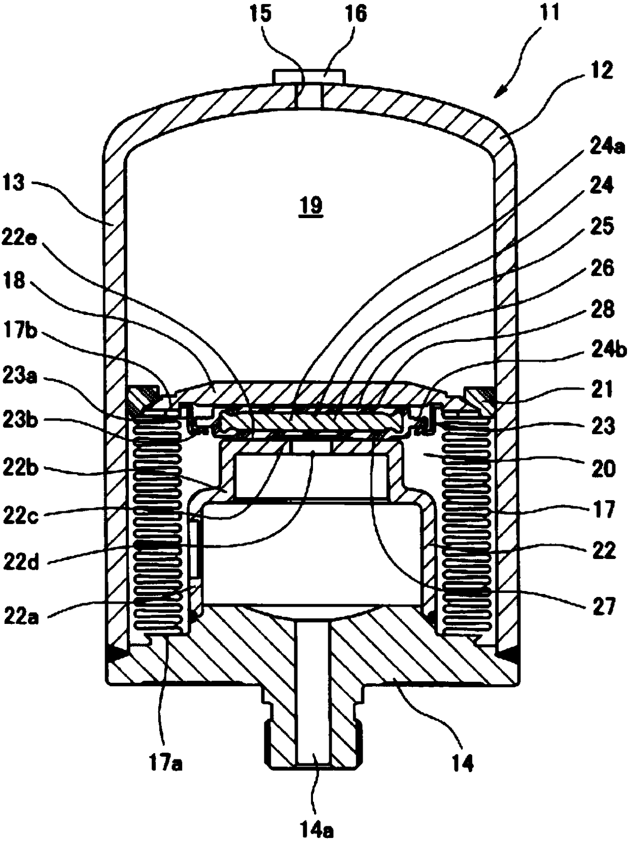
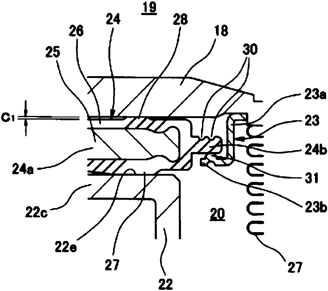
[0090] figure 1 The accumulator 11 according to the first embodiment of the present invention is shown. The enlarged section of its main part is in figure 2 shown in .

[0091] The accumulator 11 according to this embodiment is a metal bellows type accumulator using a metal bellows as the bellows 17, and is configured as follows.

[0092] That is, an accumulator case 12 having an oil port 14 connected to a pressure pipe not shown is provided, and a bellows 17 and a bellows cover 18 are arranged inside the case 12, and the internal space of the case 12 It is divided into a gas chamber 19 in which a high-pressure gas (for example, nitrogen gas) is sealed, and a liquid chamber 20 connected to a port hole 14 a of the oil port 14 . As the housing 12, a housing composed of a combination of a bottomed cylindrical housing 13 and an oil port 14 fixed (welded) to the opening of the housing 13 is depicted, but the components of the housing 12 are assigned The structure is not parti...

no. 2 example …

[0117] Figure 6 to Figure 8 An accumulator 11 according to a second embodiment of the present invention is shown. The accumulator 11 according to this second embodiment has a configuration different from that of the accumulator 11 according to the first embodiment described above in the following points.

[0118] That is, if Image 6 As shown, in the configuration of the seal bracket 23, the same bellows cover 18 side (upper side) is provided on the inward flange-shaped outer peripheral side engaging portion (first outer peripheral side engaging portion) 23b. The inward flange-shaped second outer peripheral engaging portion 23c is disposed between the inner peripheral engaging portion 24b of the packing 24 between the outer peripheral engaging portions 23b, 23c.

[0119]In the case of the seal holder 23, an inward flange-shaped outer peripheral engaging portion 23b is integrally formed at one end (lower end) of the cylindrical mounting portion 23a toward the radially inner s...


PUM


Abstract

The present invention provides an accumulator which reduces the number of components in a mechanism for absorbing pressure fluctuations during liquid expansion, simplifies assembly, and reduces component costs. In order to do so, this accumulator has a seal holder provided in a bellows cap, and a plate-shaped seal held by the seal holder. The seal holder is provided with an inward-facing flange-shaped outer-circumferential-side engaging part, while the seal is provided with an outward-projection-shaped inner-circumferential-side engaging part which comprises a rubber elastic, engages the outer-circumferential-side engaging part, and is provided on the outer circumference of the seal body. When a liquid expands inside a liquid chamber while the liquid chamber is closed, the outer-circumferential-side engaging part elastically deforms the inner-circumferential-side engaging part, the seal remains seated on the seating surface as a result of the difference between the pressure-receiving surface areas on both surfaces thereof, and the bellows cap moves to a position at which the liquid pressure and the gas pressure are balanced.

Description

[0001] This application is a divisional application of the Chinese patent application with the application number 201580008784.5, the application date is March 11, 2015, and the invention name is "accumulator". technical field [0002] The invention relates to an accumulator used as a pressure accumulator or a pulsation pressure attenuation device. The accumulator of the present invention is used, for example, in hydraulic piping and the like in vehicles such as automobiles. Background technique [0003] The inventors of this application have previously proposed Figure 9 to Figure 11 The accumulator 51 shown in , the accumulator 51 according to this prior art is structured as follows (refer to Patent Document 1). [0004] (i) That is, if Figure 9 As shown, the accumulator 51 has: an accumulator case 52 with an oil port 53 connected to a pressure pipe; A liquid inlet and outlet 54c is provided on the end surface 54b at the front end of the part 54a; the bellows 55 is disp...

Claims


Application Information

Patent Timeline
Patent Type & Authority Applications(China)
IPC IPC(8): F15B1/10
CPCF15B1/103F15B20/007F15B2201/3153F15B2201/41F15B1/021
Inventor 有川达浩
Owner EAGLE INDS
Why Eureka
Try Eureka