Patch infrared diode

A diode and infrared technology, applied in electrical components, circuits, semiconductor devices, etc., can solve problems such as poor reflection and refraction effects, and the product's Y-axis angle cannot meet customer needs, and achieve the effect of changing the luminous angle and improving luminous intensity.

Inactive Publication Date: 2018-07-17
GUANGDONG SHENLAITE SCI & TECH
View PDF0 Cites 2 Cited by
  • Summary
  • Abstract
  • Description
  • Claims
  • Application Information

AI Technical Summary

Problems solved by technology

However, the current SMD infrared LED structure causes the Y-axis angle of the product to fail to meet customer needs.
[0003] Existing SMD infrared LEDs, such as figure 1 As shown, it does not have a metal reflective cup as the light-emitting reflection and refraction medium of the chip, so the light emitted by the chip has poor reflection and refraction effects due to the characteristics of the substrate material, so that the luminous radiation intensity and angle of the LED in this way are mainly determined by the secondary ball. determined by the head and the chip itself

Method used


Image

  • Patch infrared diode
  • Patch infrared diode
  • Patch infrared diode

Examples


Embodiment Construction

[0018] The technical solutions of the present invention will be further described below in conjunction with the accompanying drawings and through specific implementation methods.

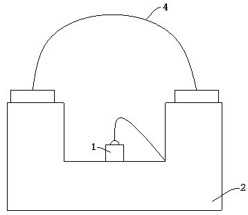
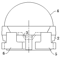
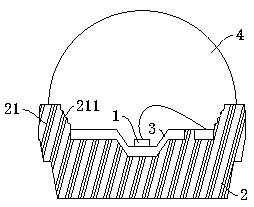
[0019] combine Figure 1 to Figure 4 As shown, this embodiment provides a chip infrared diode, including LED chips 1, and a base 2 for carrying the LED chips 1, a metal reflective cup 3 is buried on the light-emitting side of the base 2, and the metal The bottom of the reflective cup 3 is provided with the LED chip 1, the top of the metal reflective cup 3 is packaged with an optical lens 4, and the metal reflective cup 3 extends outwards with metal contacts, and the metal contacts are connected to the The terminals of the LED chip 1 are electrically connected to form soldering feet of the patch infrared diode.

[0020] Specifically, in this embodiment, a pit is provided in the middle of the upper surface of the base 2, and the metal reflective cup 3 is provided in the pit, and the edges around the ...


PUM


Abstract

The invention discloses a patch infrared diode. The patch infrared diode comprises an LED chip and a substrate used for bearing the LED chip; a metal reflective cup is embedded in the light output side of the substrate; the LED chip is arranged at the cup bottom of the metal reflective cup; an optical lens is packaged on the top of the metal reflective cup; a metal contact extends outwardly from the metal reflective cup; and the metal contact is electrically connected with the wiring end of the LED chip to form a welding pin of the patch infrared diode. By adoption of the structural design, the light from the chip is reflected and refracted by the metal reflective cup to be concentrated to the optical lens, thereby improving light emitting intensity and changing the light emitting angle.

Description

technical field [0001] The invention relates to the technical field of LEDs, in particular to a patch infrared diode. Background technique [0002] With the improvement of LED technology and the reduction of cost, in the foreseeable future, SMD infrared LED light source is bound to replace the current in-line LED and become an important component in the application field of infrared LED. Due to the characteristics of small size, convenient assembly, and high assembly reliability, infrared SMD LEDs are increasingly used in a wide range of applications. However, the current SMD infrared LED structure causes the Y-axis angle of the product to fail to meet customer needs. [0003] Existing SMD infrared LEDs, such as figure 1 As shown, it does not have a metal reflective cup as the light-emitting reflection and refraction medium of the chip, so the light emitted by the chip has poor reflection and refraction effects due to the characteristics of the substrate material, so that ...

Claims


Application Information

Patent Timeline
Patent Type & Authority Applications(China)
IPC IPC(8): H01L33/62H01L33/60H01L33/58H01L33/48
CPCH01L33/62H01L33/48H01L33/58H01L33/60
Inventor 谢安全
Owner GUANGDONG SHENLAITE SCI & TECH
Why Eureka
Try Eureka