Supercharge Your Innovation With Domain-Expert AI Agents!

Magnetic resonance imaging system and related methods

A magnetic resonance imaging and magnetic core technology, applied in the direction of measuring magnetic variables, magnetic sensor arrays, magnetic sensor housings, etc., can solve the problem of image quality damage

Active Publication Date: 2021-12-28
GENERAL ELECTRIC CO
View PDF5 Cites 0 Cited by
  • Summary
  • Abstract
  • Description
  • Claims
  • Application Information

AI Technical Summary

Problems solved by technology

Therefore, the quality of the acquired image is compromised

Method used


Image

  • Magnetic resonance imaging system and related methods
  • Magnetic resonance imaging system and related methods
  • Magnetic resonance imaging system and related methods

Examples


Embodiment Construction

[0021] Unless defined otherwise, technical and scientific terms used herein have the same meaning as commonly understood by one of ordinary skill in the art to which this specification belongs. As used herein, the terms "first", "second", etc. do not indicate any order, quantity or importance, but are actually used to distinguish one element from another element. Also, the terms "a, an" do not denote a limitation of quantity, but rather denote the presence of at least one of the mentioned items. The term "or" is intended to be inclusive and mean one, some, or all of the listed items. Use of "including, comprising" or "having" and variations thereof herein is intended to cover the items listed thereafter and their equivalents as well as additional items. The terms "connected" and "coupled" are not limited to physical or mechanical connections or connections, and may include electrical connections or connections, whether direct or indirect. Furthermore, terms such as "circuit,...


PUM


Abstract

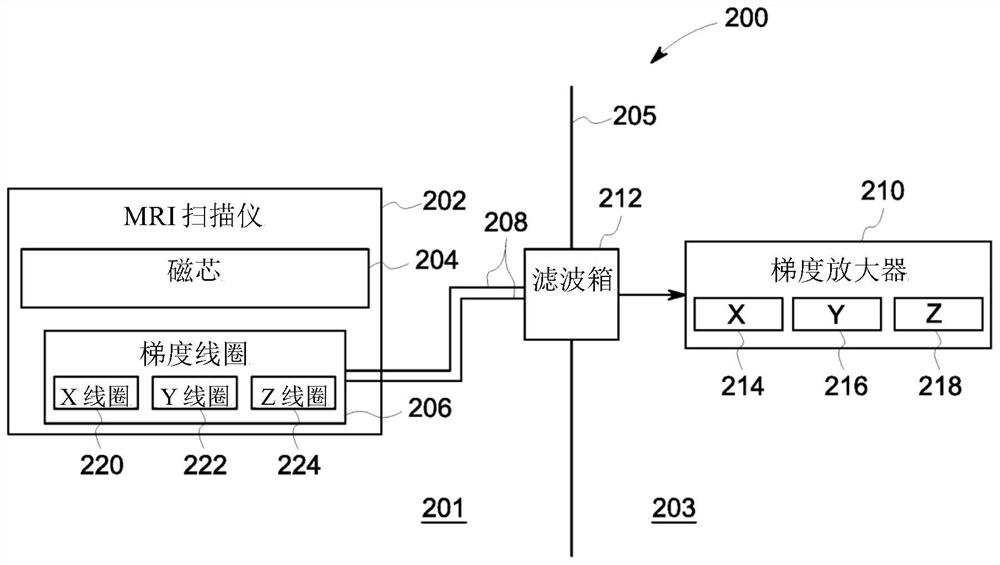
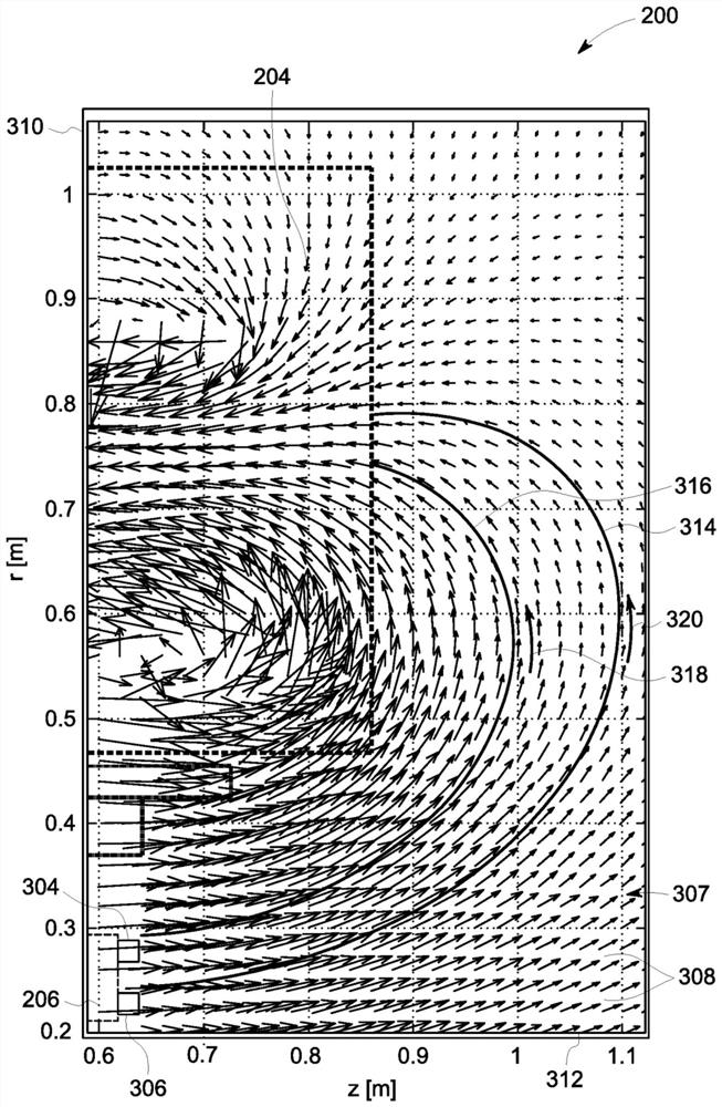
A magnetic resonance imaging system is disclosed. A magnetic resonance imaging system includes a magnetic core that generates a magnetic field including a plurality of magnetic field lines. The magnetic resonance imaging system also includes a plurality of gradient coils disposed along the magnetic core, and a plurality of gradient amplifiers. Additionally, the magnetic resonance imaging system includes a plurality of bus bar conductors connecting corresponding gradient coils of the plurality of gradient coils and corresponding gradient amplifiers of the plurality of gradient amplifiers. The plurality of busbar conductors are positioned along at least one of a first path extending along the plurality of magnetic field lines and a second path extending in a substantially linear direction from the corresponding gradient coil to an edge region of the magnetic field to reduce Lorentz forces Effect on multiple busbar conductors.

Description

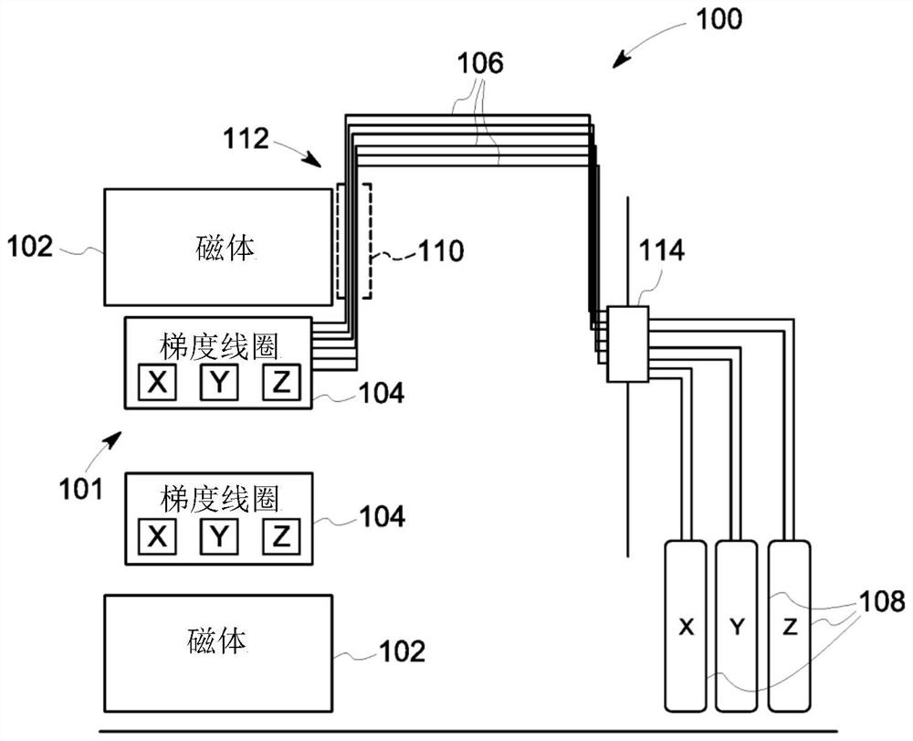
[0001] Cross References to Related Applications [0002] This application claims priority to US Patent Application No. 14 / 938,891, filed November 12, 2015, which is hereby incorporated by reference in its entirety. technical field [0003] Embodiments of the present invention relate generally to magnetic resonance imaging systems, and more particularly to busbar conductors for use in magnetic resonance imaging systems. Background technique [0004] In a magnetic resonance imaging (MRI) system, electrical bus-bar conductors carry electrical current from a gradient driver to a gradient coil. In inserted gradient coil MRI systems, the gradient coils are often much shorter than the magnetic core. Therefore, the busbar conductors need to extend significantly closer to the iso-center of the magnets to facilitate connection to the gradient coils. In particular, considerable lengths of busbar conductors are arranged in the area that is affected by the strong magnetic field genera...

Claims


Application Information

Patent Timeline
Patent Type & Authority Patents(China)
IPC IPC(8): A61B5/055G01R33/00
CPCG01R33/3858G01R33/3802G01R33/3852G01R33/3854A61B5/055G01R33/0023G01R33/0047G01R33/0094
Inventor S-K.李E.菲夫兰J.皮尔B.科利克
Owner GENERAL ELECTRIC CO
Features
  • R&D
  • Intellectual Property
  • Life Sciences
  • Materials
  • Tech Scout
  • Unparalleled Data Quality
  • Higher Quality Content
  • 60% Fewer Hallucinations
Learn More