
Cyclones and vacuum cleaners

A technology of cyclone separation device and cyclone separator, which is applied in the direction of vacuum cleaners, suction filters, household appliances, etc., and can solve the problems of large air volume loss, large volume and space occupied by the first separation unit, etc.

Active Publication Date: 2021-04-09
JIANGSU MIDEA CLEANING APPLIANCES +1
View PDF6 Cites 0 Cited by
  • Summary
  • Abstract
  • Description
  • Claims
  • Application Information

AI Technical Summary

Problems solved by technology

[0003] For example, multiple secondary cyclones are arranged inside the upper cylinder of the primary cyclone, and some of them are plugged into the lower cylinder. The overall structure is relatively complicated, taking up too much space, the air passage is small, and the dust collection performance is average; the second The first-stage separation device is above the dust bucket, and part of its structure is inserted into the first separation unit. From the appearance, it is equivalent to being exposed to the outside, with a complex structure and high requirements for sealing; the first-stage dust chamber is in the first separation unit. Outside, the dust chamber of the second stage is inside the first separation unit, the structure is relatively complicated, it is not easy to clean and disassemble, and the first separation unit occupies a large volume, which makes the volume of the first stage dust chamber small; the first separation unit The mesh cover attached to the surface has many meshes and occupies a large area. It is more difficult to clean up when it is blocked by dust, which is time-consuming and laborious; Small, resulting in large air volume loss, poor dust absorption performance, and there is room for improvement

Method used


Image

  • Cyclones and vacuum cleaners
  • Cyclones and vacuum cleaners
  • Cyclones and vacuum cleaners

Examples


Embodiment Construction

[0047] Embodiments of the present invention are described in detail below, examples of which are shown in the drawings, wherein the same or similar reference numerals designate the same or similar elements or elements having the same or similar functions throughout. The embodiments described below by referring to the figures are exemplary only for explaining the present invention and should not be construed as limiting the present invention.

[0048] In describing the present invention, it should be understood that the terms "center", "longitudinal", "transverse", "length", "width", "thickness", "upper", "lower", "front", " Back", "Left", "Right", "Vertical", "Horizontal", "Top", "Bottom", "Inner", "Outer", "Clockwise", "Counterclockwise", "Axial", The orientation or positional relationship indicated by "radial", "circumferential", etc. is based on the orientation or positional relationship shown in the drawings, and is only for the convenience of describing the present invent...


PUM


Abstract

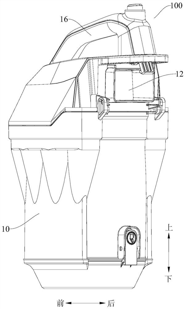
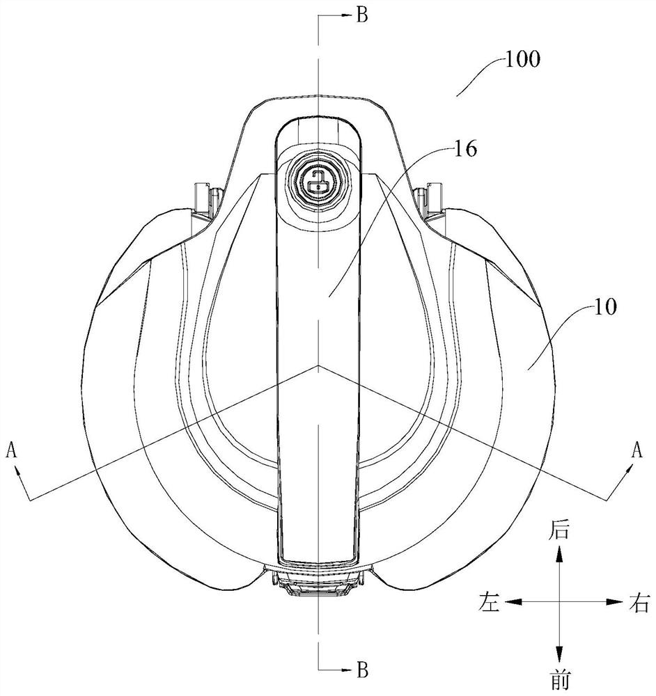
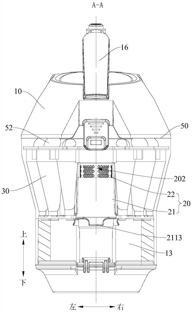
The invention discloses a cyclone separation device and a vacuum cleaner. The cyclone separation device comprises: a casing, a cyclone separation unit, the cyclone separation unit is arranged in the casing to separate dirt from the dust-laden airflow, and the cyclone separation unit includes a first-stage cyclone A separator, a plurality of second-stage cyclone separators located downstream of the first-stage cyclone separator in the direction of airflow flow, and an air outlet between the first-stage cyclone separator and the plurality of second-stage cyclone separators, a plurality of The second-stage cyclone separator surrounds the first-stage cyclone separator, wherein the first-stage cyclone separator includes an air guide channel and a first-stage cyclone channel surrounding a part of the air guide channel, and the dust-laden airflow enters the first stage from the air guide channel After the cyclone channel is cyclone separated, part of it enters the second-stage cyclone separator through the air guide channel again, and the other part enters the second-stage cyclone separator through the air outlet. According to the cyclone separation device of the embodiment of the present invention, the effect of dust removal is good.

Description

technical field [0001] The invention relates to the technical field of vacuum cleaners, in particular to a cyclone separation device and a vacuum cleaner. Background technique [0002] At present, the vacuum cleaners in the related art begin to adopt the device of the multi-stage cyclone separation system, which is composed of a single first separation unit and a plurality of second cyclone separation units, and the second cyclone separation unit contains a plurality of second cyclone separation devices, but the existing The device has many problems. [0003] For example, multiple secondary cyclones are arranged inside the upper cylinder of the primary cyclone, and some of them are plugged into the lower cylinder. The overall structure is relatively complicated, taking up too much space, the air passage is small, and the dust collection performance is average; the second The first-stage separation device is above the dust bucket, and part of its structure is inserted into t...

Claims


Application Information

Patent Timeline
Patent Type & Authority Patents(China)
IPC IPC(8): A47L9/16
CPCA47L9/1608A47L9/165A47L9/1658
Inventor 戴君鲍辉方杰
Owner JIANGSU MIDEA CLEANING APPLIANCES
Learn More