
An electrical automation industrial dust removal device

A technology of electrical automation and dust removal device, which is applied in combination devices, chemical instruments and methods, separation methods, etc., can solve the problems of high energy consumption, high cost of small and medium-sized enterprises, complex structure of dust collection devices in workshops, etc., to improve dust collection efficiency. Effect

Inactive Publication Date: 2020-06-30
NANJING INST OF RAILWAY TECH
View PDF5 Cites 2 Cited by
  • Summary
  • Abstract
  • Description
  • Claims
  • Application Information

AI Technical Summary

Problems solved by technology

[0002] The types of dust removal devices can be divided into bionano film dust suppression devices, cloud and fog dust suppression devices, bag dust removal devices, cyclone dust removal devices, wet dust removal devices, electrostatic dust removal devices, desulfurization and dust removal devices, which are used in chemical industry, metallurgy, construction, machinery, light In textile and other industries, although the existing automatic dust removal technology can greatly improve labor productivity and liberate people from heavy physical labor and harsh and dangerous working environments, the existing workshop dust removal device only removes the dusty gas in the workshop. After treatment, it is directly discharged outside the workshop. Although the environment of the workshop can be improved, the solid particles in the air have not been treated, and thus are scattered in the air, which cannot meet the current environmental protection standards. In addition, the existing workshop dust collection device has a complex structure. High cost and high energy consumption, the cost is too high for small and medium-sized enterprises to bear

Method used


Image

  • An electrical automation industrial dust removal device
  • An electrical automation industrial dust removal device
  • An electrical automation industrial dust removal device

Examples


Embodiment

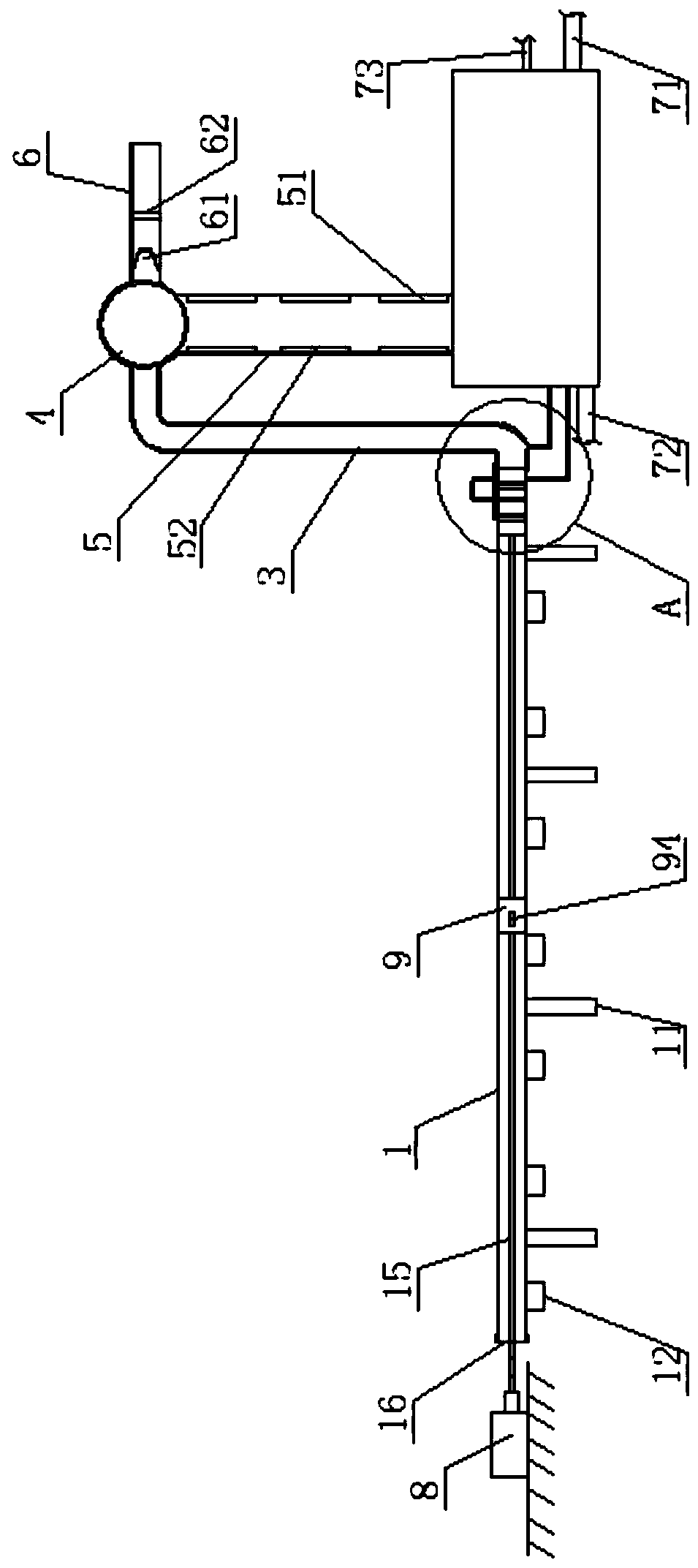
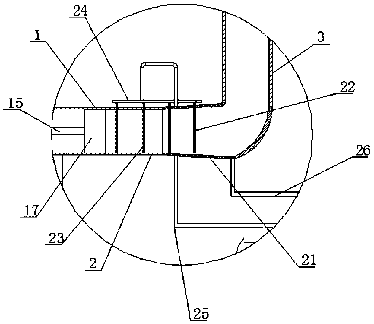
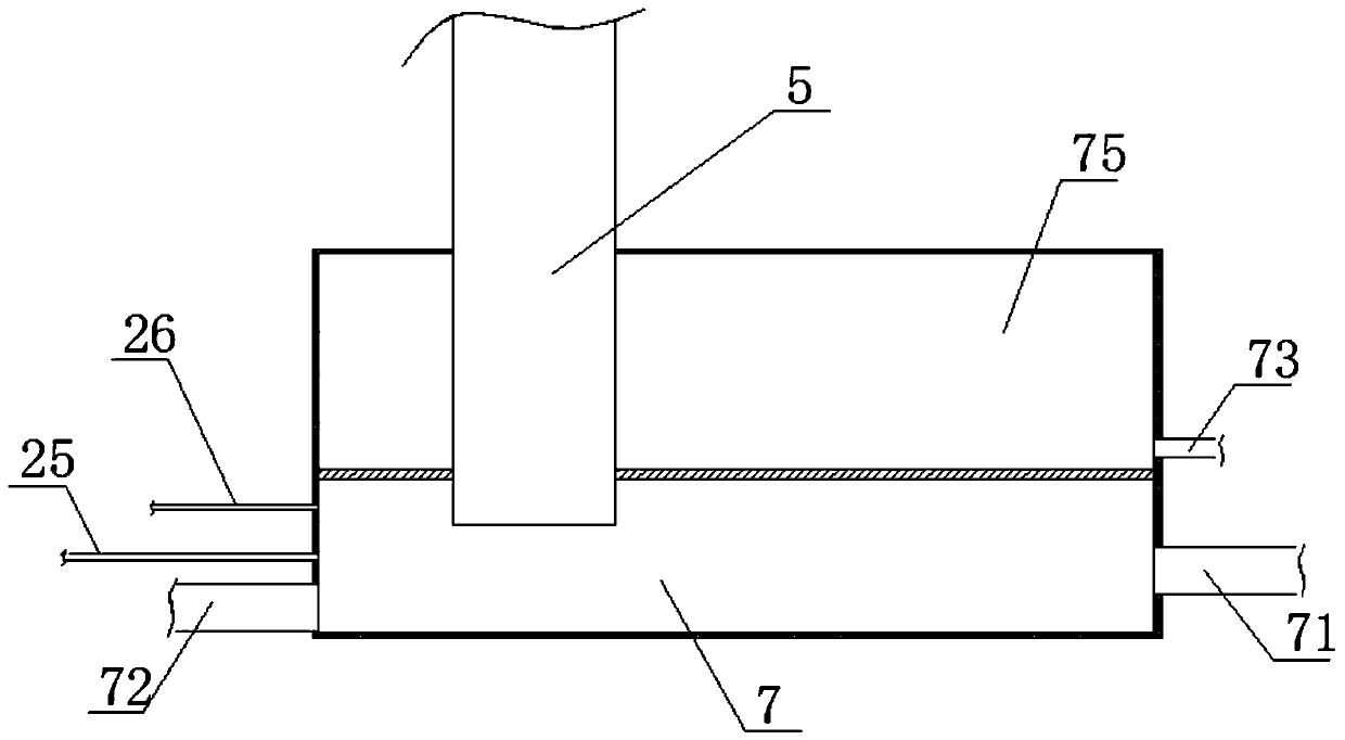
[0034] An electrical automation industrial dust removal device, including a dust suction device and a dust collection device, the dust collection device includes a dust collection box, and the dust collection box is divided into a sedimentation chamber 7 containing liquid, and the precipitation chamber 7 is equipped with a Dismounted see-through glass, the top of the settling chamber 7 is provided with a filter screen; the liquid in the settling chamber 7 can be water or water with adsorbent or be filled with weakly alkaline or weakly acidic liquid according to the working environment of the workshop, so Liquid outlet pipe 25, liquid inlet pipe 26, liquid replenishment pipe 71 and liquid discharge pipe 72 are set on the side wall of the precipitation chamber 7, and the liquid in the precipitation chamber 7 is replenished or drained through the liquid replenishment pipe 71 and liquid discharge pipe 72. A water pump is arranged on the liquid outlet pipe 25, a water distribution p...


PUM


Abstract

The invention discloses an electrically automatic industrial dust removing device. The device comprises a dust sucking device and a dust collecting device, wherein the dust collecting device comprisesa dust collecting box; the dust sucking device comprises a ventilation pipe, a first dust collecting pipe, a second dust collecting pipe and an air outlet pipe; an electrostatic adsorption system isarranged in the second dust collecting pipe, a dust collecting chamber is arranged at the top end of the second dust collecting pipe, the air outlet pipe is connected with an air outlet, a filtering device is arranged in the air outlet pipe, a first tapered pipe is connected with the air inlet through a vertical pipe, the bottom end of the second dust collecting pipe extends into a dust collectingbox and extends to the lower side of the liquid level, a liquid inlet pipe is communicated with the first dust collecting pipe through a through hole, and the through hole is higher than the liquid level in a settling chamber. The device has the benefits as follows: the device is simple in structure and easy to operate, and gas entering a gas exhaust pipe has very low dust content after being filtered by the filtering device and can be exhausted to the air directly.

Description

technical field [0001] The invention mainly relates to a dust removal device, in particular to an electrical automation industrial dust removal device. Background technique [0002] The types of dust removal devices can be divided into bionano film dust suppression devices, cloud and fog dust suppression devices, bag dust removal devices, cyclone dust removal devices, wet dust removal devices, electrostatic dust removal devices, desulfurization and dust removal devices, which are used in chemical industry, metallurgy, construction, machinery, light In textile and other industries, although the existing automatic dust removal technology can greatly improve labor productivity and liberate people from heavy physical labor and harsh and dangerous working environments, the existing workshop dust removal device only removes the dusty gas in the workshop. After treatment, it is directly discharged outside the workshop. Although the environment of the workshop can be improved, the s...

Claims


Application Information

Patent Timeline
Patent Type & Authority Patents(China)
IPC IPC(8): B01D50/00
CPCB01D50/00
Inventor 朱颖莉李志明
Owner NANJING INST OF RAILWAY TECH
Learn More