Low temperature environment test chamber and low temperature environment test method

A low-temperature environment and test chamber technology, which is applied in the field of low-temperature environment test chambers, can solve the problems that it is difficult to ensure a rapid response to the experimental temperature and the rapid response to the ambient temperature is difficult to achieve, and achieve the effect of rapid temperature response

Inactive Publication Date: 2018-07-20
北京长征天民高科技有限公司
View PDF5 Cites 6 Cited by
  • Summary
  • Abstract
  • Description
  • Claims
  • Application Information

AI Technical Summary

Problems solved by technology

[0004] However, traditional low-temperature test equipment usually can only provide a small test space to meet the test requirements of small test pieces, and it is difficult to meet the needs of large-scale test pieces in specific low-temperature environments. For example, the announcement number is "CN204988323U", which discloses the name It is a Chinese patent for "an adjustable ultra-low temperature environment experimental device", which mainly includes a low-pressure chamber and a Dewar bottle arranged coaxially. Multiple heating devices in the low-voltage chamber increase the temperature of the low-voltage chamber. In order to ensure the rapid response of the test temperature, the device can only provide a small test space for the test needs of small instruments such as circuit boards, tap so

Method used


Image

  • Low temperature environment test chamber and low temperature environment test method
  • Low temperature environment test chamber and low temperature environment test method
  • Low temperature environment test chamber and low temperature environment test method

Examples


Embodiment Construction

[0065] The technical solution of the present invention will be described in detail below in conjunction with the drawings and specific embodiments, but it is not intended to limit the present invention.

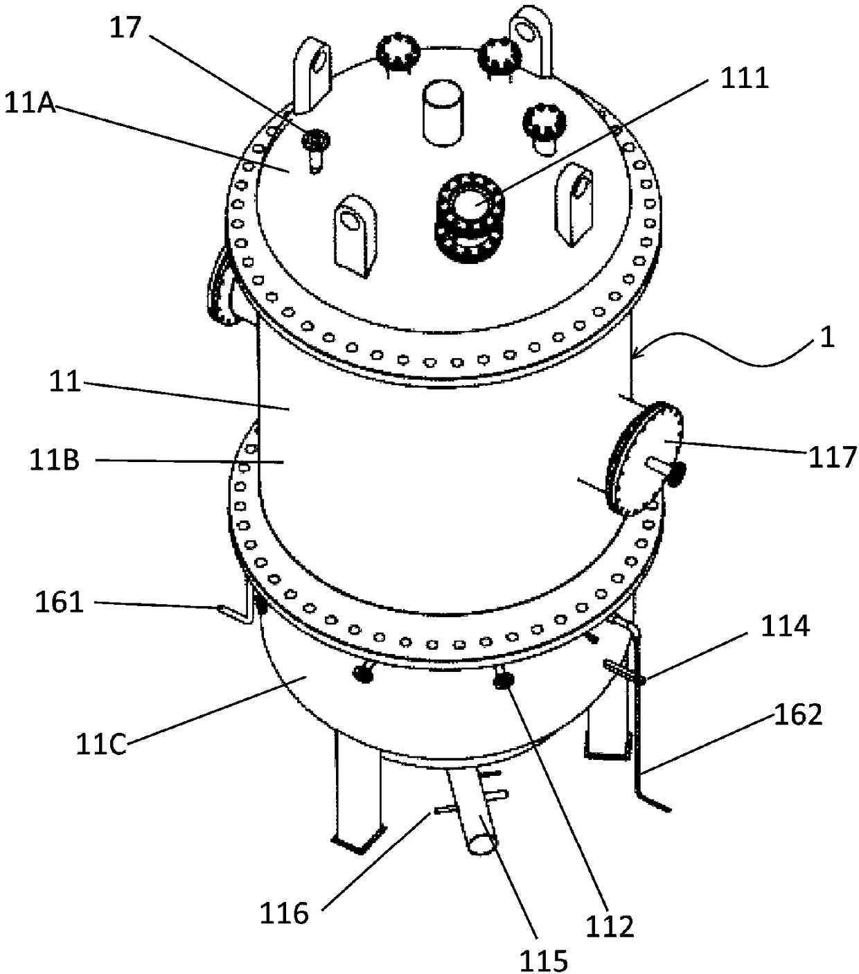
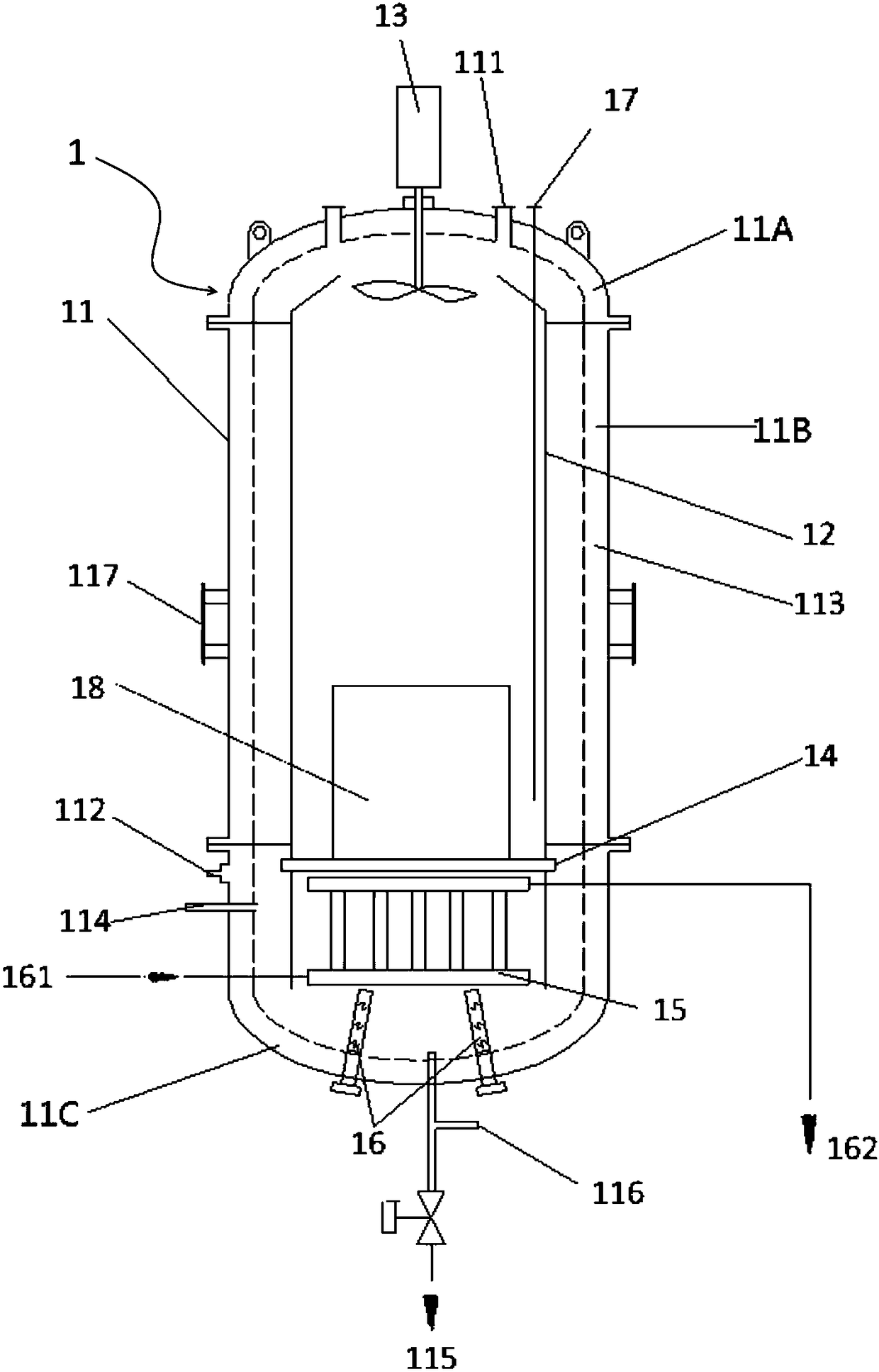
[0066] Please also see figure 1 with figure 2 , figure 1 It is a perspective view of a low temperature environment test chamber according to an embodiment of the present invention, figure 2 It is a structural schematic diagram of a low-temperature environment test chamber according to an embodiment of the present invention. Such as figure 2 As shown, the low temperature environment test chamber 1 has a shell 11, which provides a reliable test space for the low temperature environment and withstands internal pressure. The shell 11 includes an upper head 11A, a straight section 11B and a lower head 11C from top to bottom. The head 11A, the lower head 11C and the straight section 11B are connected by flanges; the inner air duct 12 is sleeved in the housing 11, and the inn...


PUM


Abstract

The invention discloses a low temperature environment test chamber and a low temperature environment test method. The low temperature environment test chamber includes a test chamber shell, a test piece mounting platform, a heat exchanger, a heating device, a temperature measuring device, a fan and an inner air duct cylinder. A test piece is arranged on the test piece mounting platform, the heat exchanger and the heating device are used to increase and decrease the temperature in the test chamber, the temperature measuring device measures the temperature in the test chamber, and the fan and the inner air duct cylinder make a circulation air duct formed in the test chamber. The method controls the temperature in the test chamber according to the temperature measured by the temperature measuring device, a target temperature and a temperature increasing and decreasing rate. A circulating air system is formed in the test chamber, so the uniformity of the temperature in the chamber is ensured, the test piece rapidly dissipates, and the quick-responding temperature increasing and decreasing process is achieved.

Description


Claims


Application Information

Patent Timeline
Owner 北京长征天民高科技有限公司
Why Eureka
Try Eureka