Improved medical test tube rack

A test tube rack and improved technology are applied in the field of medical devices to achieve the effects of not being damaged, simple in structure and low in manufacturing cost

Inactive Publication Date: 2018-07-20
杨莉
View PDF2 Cites 1 Cited by
  • Summary
  • Abstract
  • Description
  • Claims
  • Application Information

AI Technical Summary

Problems solved by technology

[0002] The test tube rack is a rack for placing test tubes. The existing test tube racks generally can only place test tubes with a specific diameter and cannot be adjusted according to the diameter of the test tube. Therefore, it is necessary to improve

Method used


Image

  • Improved medical test tube rack
  • Improved medical test tube rack
  • Improved medical test tube rack

Examples


Embodiment Construction

[0019] The following are specific embodiments of the present invention and in conjunction with the accompanying drawings, the technical solutions of the present invention are further described, but the present invention is not limited to these embodiments.

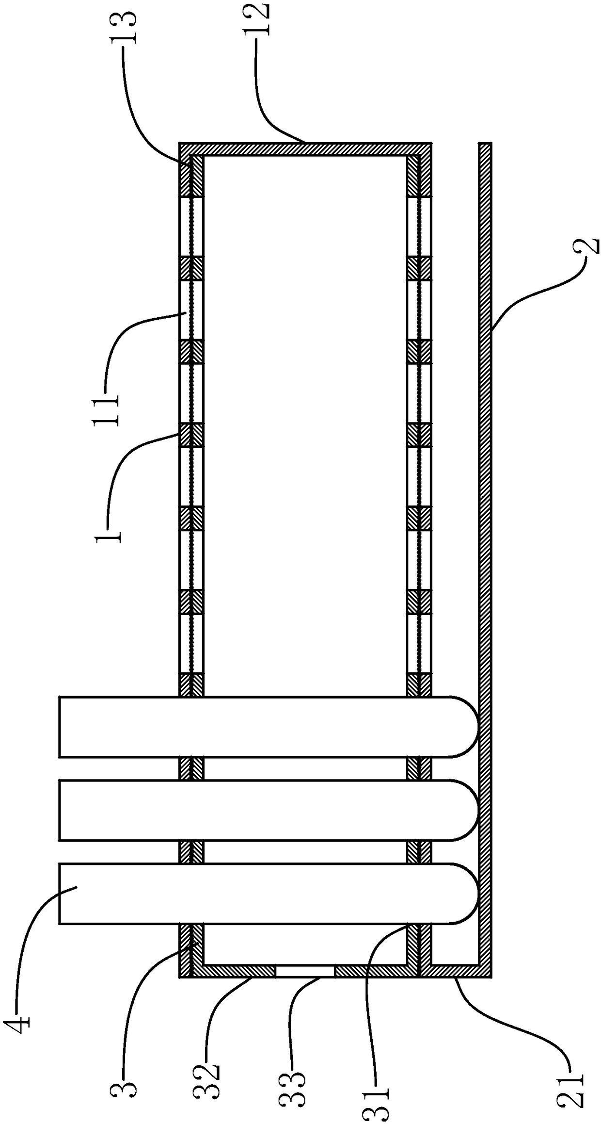
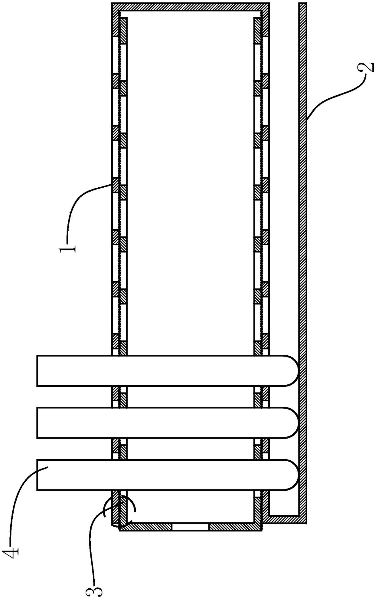
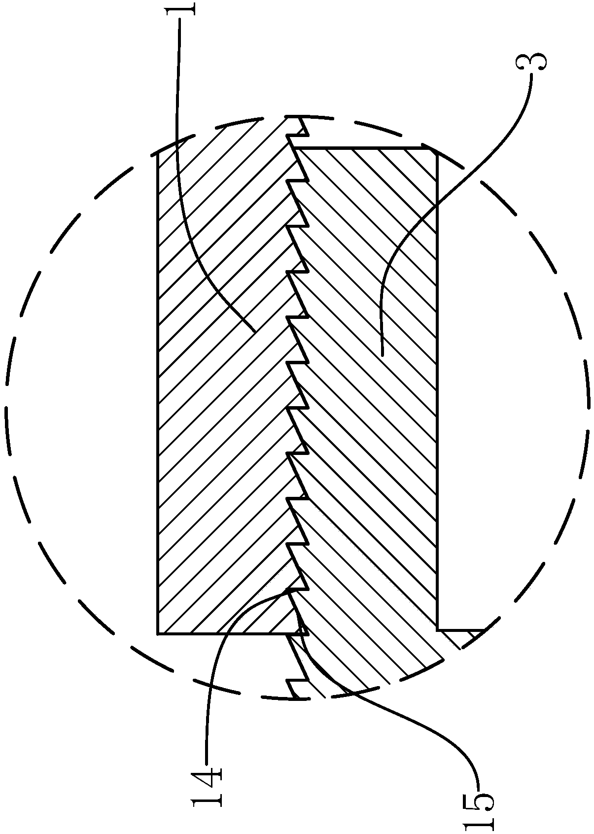
[0020] like Figure 1-3 As shown, an improved medical test tube rack of the present invention includes two support plates 1 parallel to each other and a bottom plate 2 located below the two support plates 1 in parallel, and the right sides of the two support plates 1 are connected by an upper connecting plate 12, The lower supporting plate 1 is connected to the bottom plate 2 through the lower connecting plate 21, and also includes two adjusting plates 3 parallel to each other. Hole-shaped support holes 11, two adjusting plates 3 are vertically provided with several circular hole-shaped adjusting holes 31, and the supporting holes 11 on the two supporting plates 1 are aligned in turn, and are respectively aligned with the ...


PUM


Abstract

The invention provides an improved medical test tube rack and belongs to the field of medical apparatus and instruments. The problem is solved that an existing test tube rack is monotonous in structure. The improved medical test tube rack comprises two supporting plates, a baseplate and two adjustment plates, the left side edges of the two adjustment plates are connected through a pull plate, andsupporting holes are formed in the two supporting plates; adjustment holes are formed in the two adjustment plates, the opposite sides of the two adjustment plates fit the opposite sides of the two supporting plates, and one-way teeth are arranged between the supporting plates and the adjustment plates; the one-way teeth comprise multiple strip-shaped racks which are located at the opposite sidesof the supporting plates and the adjustment plates respectively and meshed with one another, the length directions of the racks are parallel to the pull plate, the cross sections of the racks are in asawtooth shape, the racks comprise locking surfaces and adjustment surfaces, and the locking surfaces are connected with the adjustment surfaces. The test tube rack is simple in structure, the structure is conveniently adjusted, and accordingly the rack adapts to test tubes of different diameters.

Description

technical field [0001] The invention belongs to the technical field of medical instruments and relates to an improved medical test tube rack. Background technique [0002] The test tube rack is a shelf for placing test tubes. Existing test tube racks generally can only place test tubes of a specific diameter and cannot be adjusted according to the diameter of the test tubes. Therefore, it is necessary to improve. Contents of the invention [0003] The object of the present invention is to solve the above problems in the prior art, and provide an improved medical test tube rack which can adapt to test tubes with different diameters and has a simple structure and convenient adjustment. [0004] The purpose of the present invention can be achieved through the following technical solutions: an improved medical test tube rack, characterized in that it includes two support plates parallel to each other and a bottom plate parallel to the bottom of the two support plates, and ...

Claims


Application Information

Patent Timeline
IPC IPC(8): B01L9/06
CPCB01L9/06
Inventor 杨莉
Owner 杨莉
Why Eureka
Try Eureka