
3D printer rapid cooling and preheating machine base

A 3D printer and rapid cooling technology, applied in the direction of engine base, supporting machine, mechanical equipment, etc., can solve the problems of large cooling range, scalding user's printed model, affecting the quality of 3D model, etc., to save work interval time and improve work efficiency Effect

Inactive Publication Date: 2018-07-20
CHENGDU YUYUE TECH CO LTD
View PDF0 Cites 1 Cited by
  • Summary
  • Abstract
  • Description
  • Claims
  • Application Information

AI Technical Summary

Problems solved by technology

[0003] However, in the existing technology, we need to wait for a long time for the platform to cool down after the model is printed. If the cooling is not completely completed, the user may be burned or the printed model may not be accurate. The existing cooling device does not work very well. Satisfied, one is that the cooling range is too large, resulting in different cooling degrees of raw materials in different positions, and the other is that the cooling device will cause the 3D printer, especially the vibration of the extrusion nozzle, which will affect the extruded raw materials of the extrusion device. The uniformity of the 3D model affects the quality of the 3D model, but it needs to be preheated after cooling to continue printing. The length of cooling and preheating time is very necessary

Method used


Image

  • 3D printer rapid cooling and preheating machine base

Examples


Embodiment Construction

[0012] The present invention will be further elaborated below in conjunction with the accompanying drawings and specific embodiments.

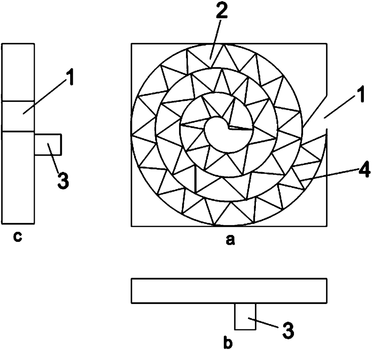
[0013] Such as figure 1 As shown, a 3D printer base includes a base body, the base body includes an inlet 1, a cooling channel 2, an outlet 3 and a heating device 4; the inlet 1 is arranged on the side of the base body; the outlet 3 is arranged on the side of the base body The bottom surface; the inside of the main body of the base is provided with a cooling passage 2 through which the inlet 1 and the outlet 3 are communicated; the inside of the cooling passage 2 is uniformly provided with a heating device 4 .

[0014] The cooling channel 2 is spiral, and the cooling channel 2 is tangent to the main body of the base.

[0015] The heating device 4 is a heating resistance wire, and the heating device 4 is evenly distributed along the spiral cooling channel 2 .

[0016] The inlet 1 is provided with a blower, and the outlet 3 is provided with an...


PUM


Abstract

The invention provides a 3D printer rapid cooling and preheating machine base. The 3D printer rapid cooling and preheating machine base comprises a base main body. The base main body comprises an inlet, a cooling channel, an outlet and heating devices. The inlet is formed in the side face of the base main body. The outlet is formed in the bottom face of the base main body. The cooling channel is formed in the base main body. The inlet communicates with the outlet through the cooling channel. The heating devices are evenly arranged in the cooling channel. According to the 3D printer rapid cooling and preheating machine base, due to the fact that the spiral cooling channel is formed in the base main body, vibration caused when a cooling medium enters is reduced, the edge of an outer circle of the cooling channel is tangential to the base main body, the effect that areas distributed evenly with the spraying position of an extruding spray nozzle as the center are the cooling ranges is ensured, and vibration is not caused to the extruding spray nozzle; and the heating devices can preheat the base rapidly after cooling, the operation interval is shortened, and the operation efficiency isimproved. Cold air is used as the cooling medium and can be repeatedly and circularly used, and energy conservation and emission reduction are achieved.

Description

technical field [0001] The invention belongs to the field of 3D advanced manufacturing, and in particular relates to a rapid cooling and preheating machine base of a 3D printer. Background technique [0002] In 3D printing technology, the extrusion equipment extrudes the raw material layer by layer according to the set path to build a three-dimensional model. In this process, as the raw material is extruded, it needs to be cooled at the same time, so that the raw material can be cooled and formed as soon as possible. . Friends who use 3D printers may know that the printing process needs to be preheated and then cooled. But every time after the model is printed, we have to wait for a long time for the platform to cool down, and then we can take the model down. [0003] However, in the existing technology, we need to wait for a long time for the platform to cool down after the model is printed. If the cooling is not completely completed, the user may be burned or the printed...

Claims


Application Information

Patent Timeline
Patent Type & Authority Applications(China)
IPC IPC(8): B29C64/20B29C64/295B29C35/16F16M5/00B33Y30/00
CPCB29C35/16B29C2035/1658B33Y30/00F16M5/00
Inventor 不公告发明人
Owner CHENGDU YUYUE TECH CO LTD
Learn More