
Brake-by-wire device for driverless racing car

An unmanned, brake-by-wire technology, applied in the field of unmanned racing car braking systems, can solve problems such as poor reliability, and achieve the effect of improving safety performance and enhancing braking reliability.

Pending Publication Date: 2018-07-20
LIAONING UNIVERSITY OF TECHNOLOGY
View PDF14 Cites 7 Cited by
  • Summary
  • Abstract
  • Description
  • Claims
  • Application Information

AI Technical Summary

Problems solved by technology

But this braking mode is less reliable

Method used


Image

  • Brake-by-wire device for driverless racing car
  • Brake-by-wire device for driverless racing car
  • Brake-by-wire device for driverless racing car

Examples


Embodiment Construction

[0038] The present invention will be further described in detail below in conjunction with the accompanying drawings, so that those skilled in the art can implement it with reference to the description.

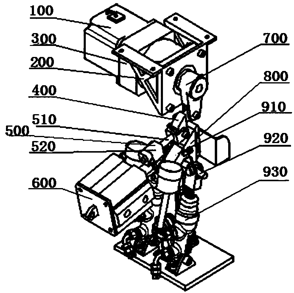
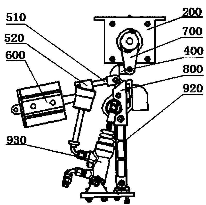
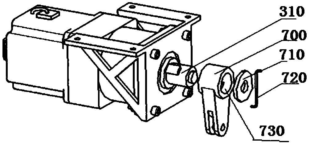
[0039] Such as Figure 1-2 As shown, the present invention provides a brake-by-wire device for an unmanned racing car, which is refitted on the original structure of the existing unmanned racing car, and it includes a motor fixing frame 200, which is installed and fixed on the on the vehicle frame and above the brake pedal 910 . The brake motor 100 is fixed in the motor fixing frame 200 by bolts, the output shaft of the brake motor 100 is provided with a speed reducer 300, the speed reducer 300 is also fixed on the motor fixing frame 200 by bolts, and the output shaft 310 of the speed reducer 300 Stretch out motor fixing frame 300 and drive rocker arm 700 and connect through flat key.

[0040] Such as Figure 3-4 As shown, the output shaft 310 of the reducer 300 is a hollo...


PUM


Abstract

The invention discloses a brake-by-wire device for a driverless racing car. The brake-by-wire device for the driverless racing car comprises a brake motor, a reducer, a driving rocker arm, a right angle pulling rod and a driving pilling plate lifting lug, wherein the reducer is fixedly connected with an output shaft of the brake motor, and two baffles are arranged near the circumference of an output shaft of the reducer in an opposite mode; one end of the driving rocker arm is fixedly connected with the output shaft of the reducer, a circular through hole is formed in the upper end of the driving rocker arm, and two grooves are formed in the inner wall of the through hole along the circumference in an opposite mode; the baffles are matched with the grooves in an opposite mode; one end of the right angle pulling rod is hinged to the other end of the driving rocker arm; and one end of the driving pulling plate lifting lug is hinged to the other end of the right angle pulling rod, and theother end of the driving pilling plate lifting lug is hinged to the upper end of a brake pedal. According to the brake-by-wire device for the driverless racing car, under the premise of braking reliability, the brake and the unmanned brake do not interfere with each other.

Description

technical field [0001] The invention relates to the technical field of an unmanned racing car, in particular to a braking system for an unmanned racing car. Background technique [0002] Unmanned driving has emerged under the development of intelligent technology and interconnection technology. In order to promote the cultivation of talents in my country's automobile industry, college students have modified the original electric racing car to study the technology of unmanned racing car. The competition requires that the driver can drive. Realize unmanned driving and participate in the student formula competition. The wire-control modification of the braking system is an important part of it. The existing unmanned racing car braking mainly adopts adding a cable in front of the brake pedal. The cable is wound around the output shaft of the motor, and the motor rotates to drive the pull The cable pulls the brake pedal to rotate for braking. However, this braking mode has poor ...

Claims


Application Information

Patent Timeline
Patent Type & Authority Applications(China)
IPC IPC(8): B60T7/12B60T13/74
CPCB60T7/12B60T13/74
Inventor 李刚张旭斌佟绍成赵德阳白鸿飞武霖曾庆东郝立国张乔
Owner LIAONING UNIVERSITY OF TECHNOLOGY
Learn More