
Electronic mechanical brake

A mechanical and brake technology, which is applied in the direction of mechanical equipment, brake actuators, gear transmission mechanisms, etc., can solve the problems of unsuccessful application of design schemes, difficult manufacturing and assembly, and large brake volume, so as to reduce assembly costs, The effect of reducing processing costs and improving transmission efficiency

Pending Publication Date: 2018-11-16
WANXIANG QIANCHAO SHANGHAI AUTOMOTIVE SYST
View PDF6 Cites 5 Cited by
  • Summary
  • Abstract
  • Description
  • Claims
  • Application Information

AI Technical Summary

Problems solved by technology

Among them, the U.S. patent No. US6158558 applied for an electromechanical brake. The electromechanical brake of this structure puts parts such as motors and gears into the brake housing without additional actuators, but its structure is relatively Complicated, the volume of the brake is also large
At present, most of the existing electromechanical brake device designs have not been successfully applied to real life due to the complexity of the structure, the large size, or the difficulty in manufacturing and assembling.

Method used


Image

  • Electronic mechanical brake
  • Electronic mechanical brake
  • Electronic mechanical brake

Examples


Embodiment Construction

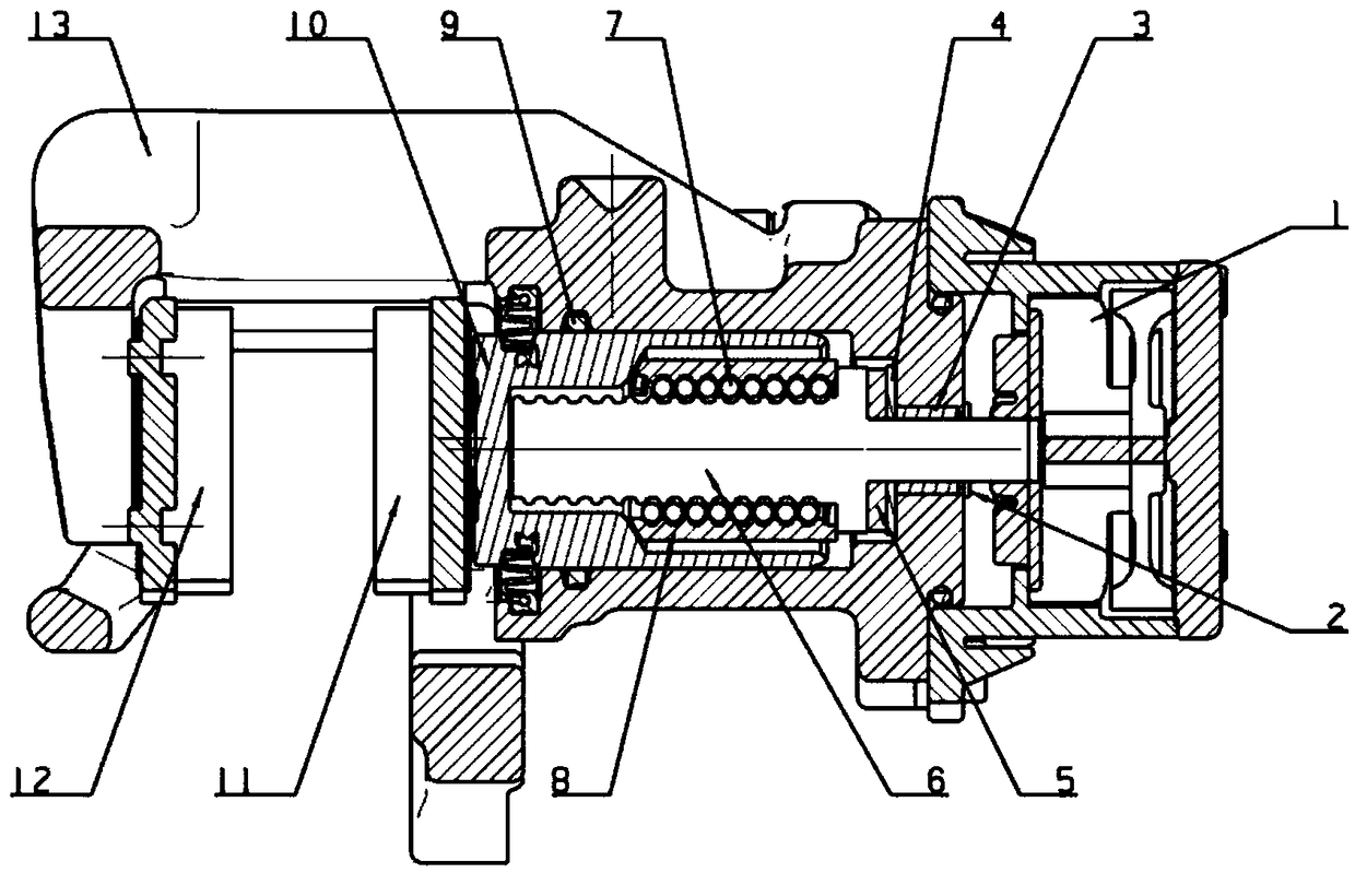
[0035] In order to make it easy to understand the technical means, creative features, goals and effects achieved by the present invention, the following examples are combined with the appended figure 1 to attach Figure 6 An electromechanical brake provided by the present invention is described in detail.

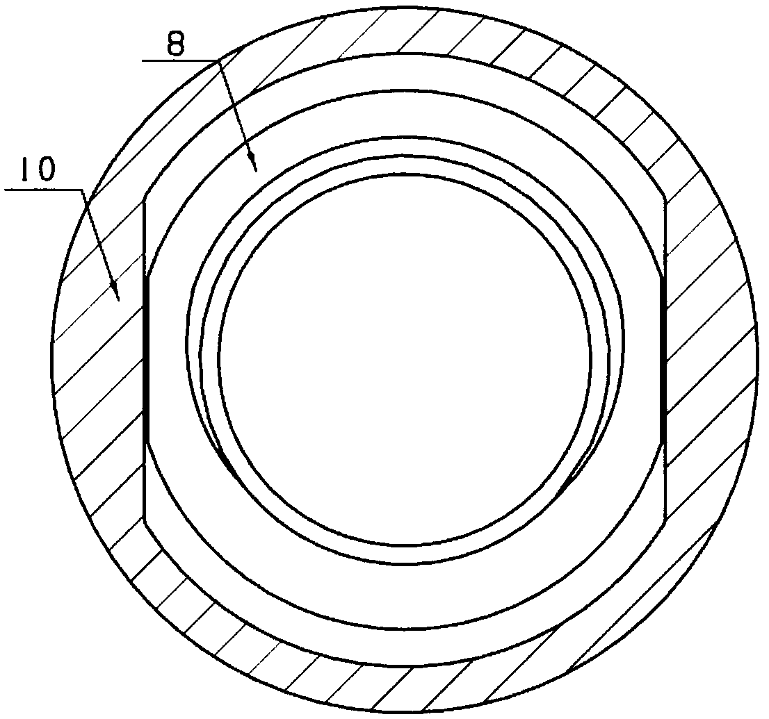
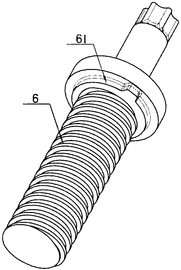
[0036] figure 1 It is a structural schematic diagram of an embodiment of an electromechanical brake of the present invention, figure 2 It is a schematic cross-sectional structure diagram of a nut and a piston in an embodiment of an electromechanical brake of the present invention, image 3 It is a structural schematic diagram of the screw rod in an embodiment of an electromechanical brake of the present invention, Figure 4 It is a structural schematic diagram of a nut in an embodiment of an electromechanical brake of the present invention, Figure 5 It is a structural schematic diagram of the screw and nut anti-rotation mechanism in an embodiment of an electromechanic...


PUM


Abstract

The invention discloses an electronic mechanical brake, and belongs to the technical field of automobile braking. The electronic mechanical brake comprises a shell, a ball screw structure and a piston. A clamp is arranged on one side of the shell and comprises two clamping claws capable of oppositely moving; each of the two clamping claws is provided with a friction plate, the two friction platesare right opposite to each other, and a penetration cylinder hole is formed in the other side of the shell. The ball screw structure is arranged in the cylinder hole and comprises a screw, a nut and aplurality of steel balls, one end of the screw penetrates out of the cylinder hole and is in driving connection with an executer, the nut can movably sleeve the outer side wall of the screw in the length direction of the screw, two clamping and connecting tables are arranged on the outer side of the nut, and the multiple steel balls are arranged between the nut and the screw. The piston is arranged in the cylinder hole, one end of the piston is connected with one clamping claw, and the other end of the piston movably makes contact with the nut in the screw length direction. According to the provided electronic mechanical brake, the structure is simplified, the integral size is reduced, and the braking efficiency is improved.

Description

technical field [0001] The invention relates to the technical field of automobile braking, in particular to an electromechanical brake. Background technique [0002] At present, with the development of automobile types, such as hybrid electric vehicles and electric vehicles that have appeared on the market today, the automobile braking system still adopts the traditional hydraulic braking technology. Although the hydraulic braking system is very mature and has high reliability, its hydraulic system pipeline is complicated, and the vacuum booster will occupy a considerable volume. That said, the hydraulic brake system, which takes up more space, is a bigger nuisance. At the same time, the hydraulic system itself also has defects such as brake fluid leakage and pollution. [0003] The electronic mechanical brake (EMB) with wire control is a good solution to the above problems. The electromechanical brake uses electric energy as the energy source, transmits electric energy t...

Claims


Application Information

Patent Timeline
Patent Type & Authority Applications(China)
IPC IPC(8): F16D65/18F16D121/14F16D125/40
CPCF16D65/18F16D2121/14F16D2125/40
Inventor 张谦邵亮
Owner WANXIANG QIANCHAO SHANGHAI AUTOMOTIVE SYST
Learn More