Brake fluid pressure control device

a technology of brake fluid and control device, which is applied in the direction of brake systems, instruments, braking components, etc., can solve the problems of the number of fluid pressure control valves that cannot receive control signals, and achieve the effect of enhancing reliability and improving fail-safe performan

Inactive Publication Date: 2007-06-12
TOYOTA JIDOSHA KK
View PDF40 Cites 6 Cited by
  • Summary
  • Abstract
  • Description
  • Claims
  • Application Information

AI Technical Summary

Benefits of technology

[0008]The invention has been made in view of the aforementioned circumstances. It is an object of the invention to improve fail-safe performance during abnormal operation of an electric system and thereby enhance reliability of a brake fluid pressure control device.
[0010]In the brake fluid pressure control device according to the first aspect of the invention, the signal lines connecting the controller to the fluid pressure control valves respectively are divided into signal line groups, each of which includes a separate connector between the controller and the fluid pressure control unit. The signal lines are not connected altogether by a single connector but are divided into a plurality of groups, which are respectively connected by separate connectors. Accordingly, even in the case where some of the connectors fall into an abnormally connected condition, for example, due to disconnection or inappropriate fitting, as long as the other connectors are normally connected, it is possible to supply control signals to the fluid pressure control valves via the signal lines connected by the connectors that are normally (correctly) connected. The fluid pressure control valves corresponding to the normally connected signal lines can be controlled, and fluid pressures in the brakes corresponding to those fluid pressure control valves can be controlled. Thus, if fail-safe performance during abnormal operation of the electric system (during abnormal operation of the control system) is improved, it is accordingly possible to enhance reliability of the brake fluid pressure control device.
[0014]In such a brake fluid pressure control device, the signal lines are divided such that one or more signal lines connected to one or more fluid pressure control valves that control fluid pressures in brakes for diagonally located wheels belong to the same group. Accordingly, even in the case where one of the connectors falls into an abnormally connected condition, if the other connector is normally connected, fluid pressures in the brakes for a pair of diagonally located wheels are controlled. Because fluid pressures in the brakes for the diagonally located wheels are controlled, it is possible to inhibit a decline in braking stability of the vehicle.
[0019]In such a brake fluid pressure control device, the signal lines for one or more fluid pressure control valves controlling fluid pressures in the brakes for the front-left and front-right wheels belong to the same group, and the signal lines for one or more fluid pressure control valves controlling fluid pressures in the brakes for the rear-left and rear-right wheels belong to the same group. Even if one of the two connectors falls into an abnormally connected condition, the brakes for the left and right wheels either on the side of the front wheels or on the side of the rear wheels can be controlled. Therefore, it is possible to inhibit a decline in braking stability.
[0041]In such fluid pressure control valves, the solenoid includes the coils connected to the different power sources. Thus, even if some of the power sources fall into an abnormal condition, it is possible to operate the movable portion and the fluid pressure control valves. It is possible to improve fail-safe performance during abnormal operation of the electric system and enhance reliability of the brake fluid pressure control device.

Problems solved by technology

However, the number of fluid pressure control valves that become incapable of receiving control signals upon occurrence of an abnormally connected condition of one connector decreases.

Method used


Image

  • Brake fluid pressure control device
  • Brake fluid pressure control device
  • Brake fluid pressure control device

Examples


Embodiment Construction

[0076]Hereinafter, a brake fluid pressure control device according to embodiments of the invention will be described in detail with reference to the drawings.

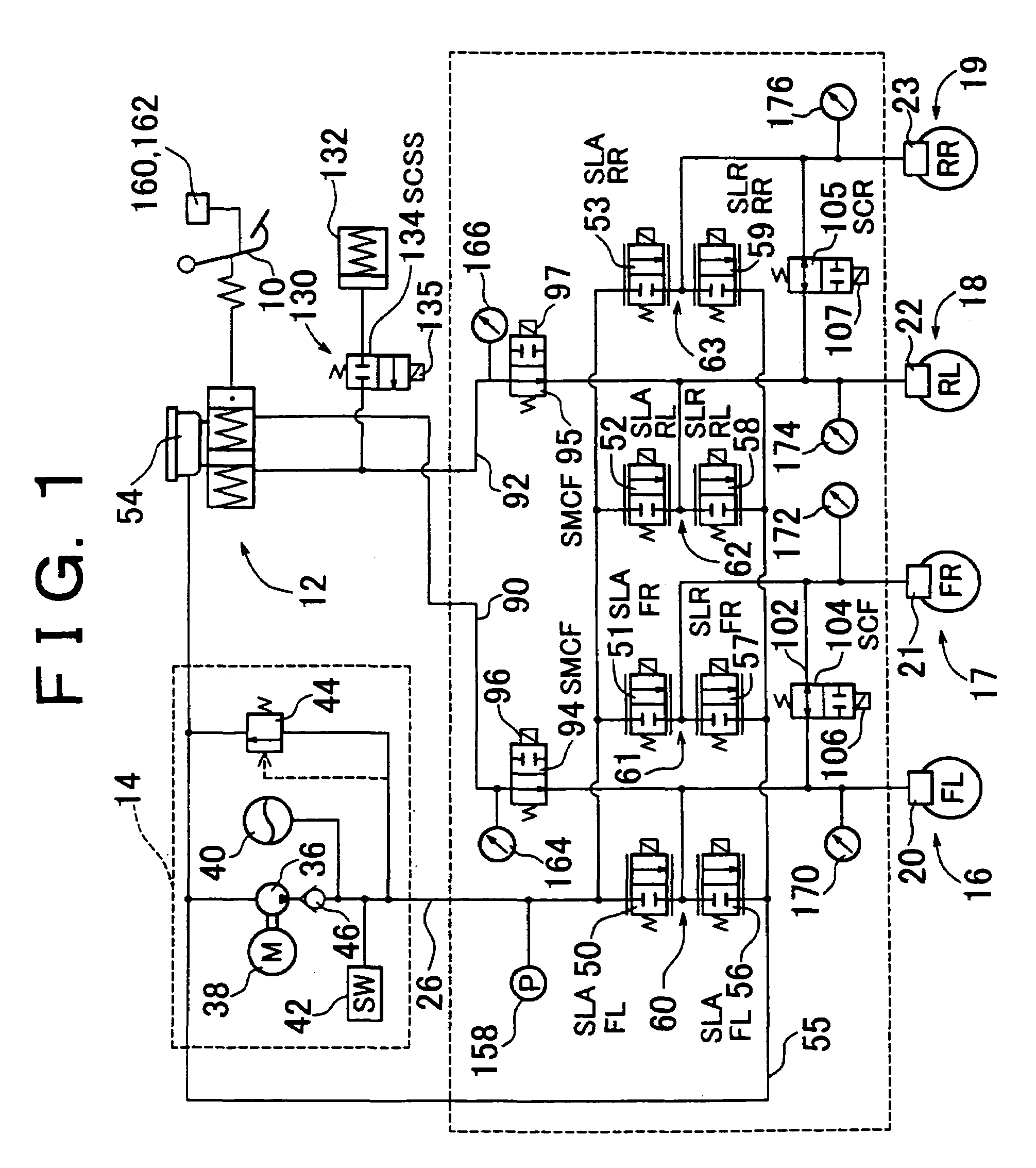
[0077]FIG. 1 shows a brake device including one embodiment of the brake fluid pressure control device. The brake device includes a brake pedal 10 serving as a brake actuating member, a master cylinder 12 including two pressurizing chambers, a power-operated pump device 14, brakes 16, 17, 18 and 19 provided in front-left, front-right, rear-left and rear-right wheels respectively, and the like. Brake cylinders 20, 21, 22 and 23 of the four brakes 16–19 are connected to the pump device 14 via a fluid passage 26. Operating fluid in the pump device 14 is supplied to the brake cylinders 20–23 via the fluid passage 26.

[0078]The pump device 14 includes a pump motor 38 for driving a pump 36. High-pressure operating fluid discharged from the pump 36 is accumulated in an accumulator 40. A pressure switch 42 detects whether or not the flui...


PUM


Abstract

A brake fluid pressure control device controls brake fluid pressures through control of fluid pressure control valves operated in accordance with control signals from, for example, a computer. Signal lines for supplying control signals to control circuits controlling coils of linear valve devices for some wheels (e.g., front-left and rear-right wheels) are connected to a brake ECU by a connector, and signal lines for supplying control signals to the control circuits controlling coils of linear valve devices for other wheels (e.g., front-right and rear-left wheels) are connected to the brake ECU by a different connector. Thus, even if one of the connectors starts operating abnormally, it is possible to supply control signals via the signal lines connected by the other connector and control linear valve devices for some of the wheels (e.g., a pair of diagonally located wheels).

Description

CROSS-REFERENCE TO RELATED APPLICATIONS[0001]This application is a Divisional of application Ser. No. 10 / 856,931 filed Jun. 1, 2004, which in turn is a Divisional of application Ser. No. 09 / 731,923, filed Dec. 8, 2000, now U.S. Pat. No. 6,761,418, issued Jul. 13, 2004 which claims priority of Japanese Patent Application No. 11-370507, filed on Dec. 27, 1999, the disclosures of which include the specification, drawings and abstract and are incorporated herein in their entirety.BACKGROUND OF THE INVENTION[0002]1. Field of the Invention[0003]The invention relates to brake fluid pressure control devices including a plurality of fluid pressure control valves that control fluid pressures in a plurality of brakes.[0004]2. Description of Related Art[0005]Japanese Laid-Open Patent Application No. 7-277175 discloses a brake fluid pressure control device including: (1) a control device mainly composed of a computer, (2) a pump that pressurizes operating fluid by means of motive power, (3) flui...

Claims


Application Information

Patent Timeline
Patent Type & Authority Patents(United States)
IPC IPC(8): B60T8/36B60T8/96B60T8/32B60T8/40B60T8/92B60T13/18B60T17/18F17D1/16
CPCB60T8/321B60T8/367B60T8/404B60T8/4081B60T13/18B60T2270/402
Inventor NAKAMURA, EIJIOTOMO, AKIHIROHIROSE, MASANORI
Owner TOYOTA JIDOSHA KK
Why Eureka
Try Eureka