Combined electronic mechanical brake

An electro-mechanical braking and compound technology, which is applied in the direction of brake type, axial brake, mechanical equipment, etc., can solve the problems of shortening life, and achieve the effects of reducing brake temperature rise, low energy consumption, and good braking effect

Inactive Publication Date: 2014-03-19
SHANDONG JIAOTONG UNIV
View PDF7 Cites 5 Cited by
  • Summary
  • Abstract
  • Description
  • Claims
  • Application Information

AI Technical Summary

Problems solved by technology

However, there is a contradiction between motor power and installation space in this mechanism, and a contradiction between deceleration and torque increase and response speed. During frequent braking, the kinematic mechanism will bear a large torque and shorten its life.

Method used


Image

  • Combined electronic mechanical brake
  • Combined electronic mechanical brake
  • Combined electronic mechanical brake

Examples


Embodiment Construction

[0023] In order to clearly illustrate the technical features of the solution, the solution will be described below through a specific implementation mode and in conjunction with the accompanying drawings.

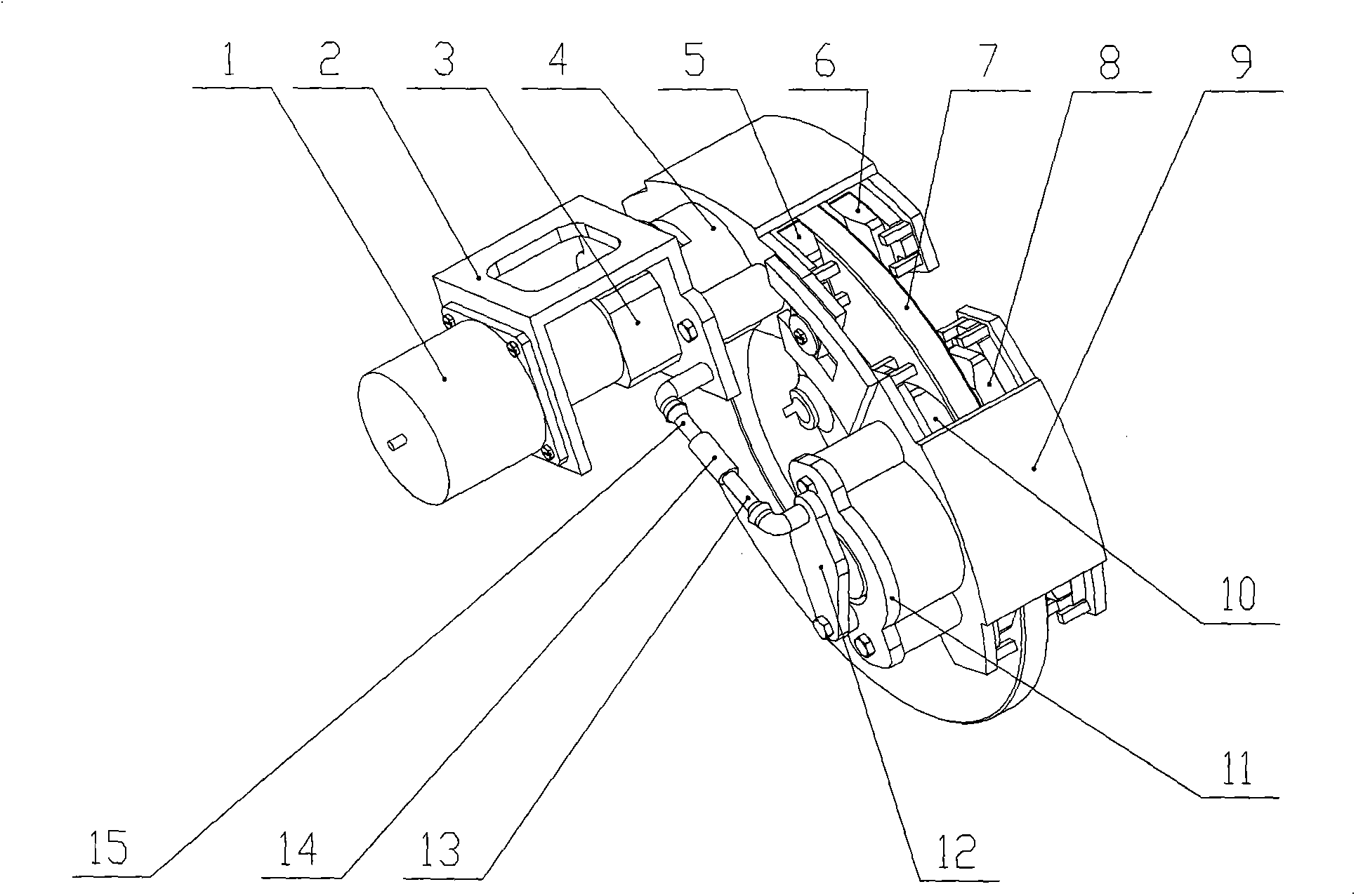
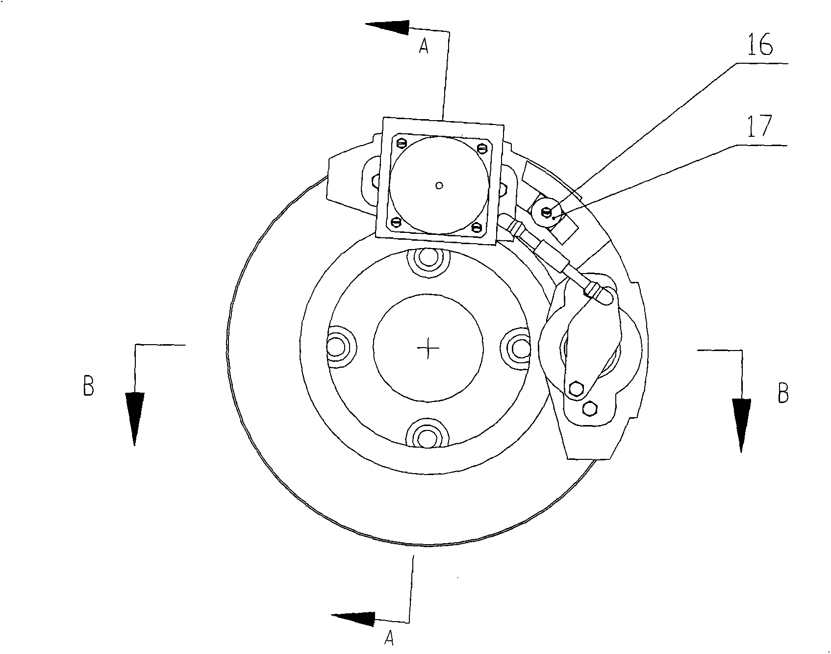
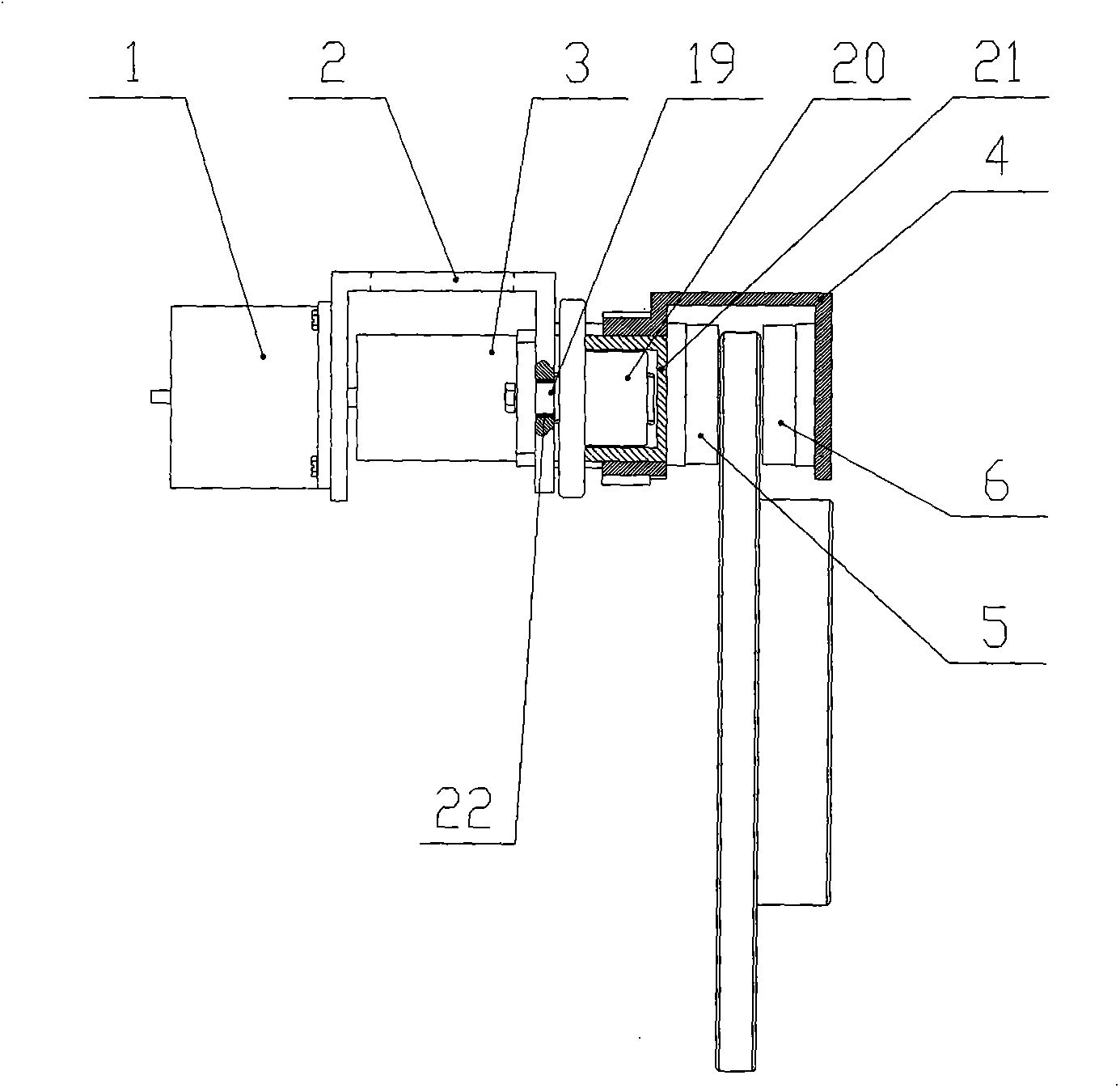
[0024] A composite electromechanical brake, consisting of a motor 1, a bracket 2, a reducer 3, a first caliper 4, a first friction plate 5, a second friction plate 6, a brake disc 7, a third friction plate 8, a second caliper 9. The fourth friction plate 10, the fixed frame 11, the thrust plate 12, the first ball rod 13, the sleeve 14, the second ball rod 15, the fixing bolt 16, the retaining ring 17, the thrust ball 18, the screw rod 19, the nut 20 , the first push cylinder 21, the wear-resistant sleeve 22, the second push cylinder 23 and the positioning bolt 24, the second caliper 9 is installed on the frame, the brake disc 7 is fixed on the axle, the third friction plate 8, the first The four friction plates 10 are respectively installed on the guide rails of the second ...


PUM


Abstract

A combined electronic mechanical brake is composed of a motor, a bracket, a speed reducer, a first clamp, a first friction plate, a second friction plate, a brake disc, a third friction plate, a second clamp, a fourth friction plate, a fixed bracket, a thrusting plate, a first ball bar, a sleeve, a second ball bar, a fixed bolt, a baffle ring, a thrusting ball, a screw rod, a nut, a first thrusting cylinder, a wear resistant sleeve, a second thrusting cylinder and a positioning bolt. When in use, the combined electronic mechanical brake can effectively reduce the motor power and save mounting space, has the advantages of low energy consumption, high response speed, convenience in maintenance, simplicity in structure, low cost and the like, can effectively utilize a force amplifying mechanism to quickly increase the braking torque, so as to conveniently realize ABS, EDB, and other integrated control, adopts multiple friction plates to effectively reduce the temperature rise during braking, increase the braking efficiency, and improve the driving safety and the braking reliability.

Description

technical field [0001] The invention relates to a vehicle brake, in particular to a composite electromechanical brake. Background technique [0002] The brake is an important part of the car, and it is a vital safety device. The quality and performance of the brake affect the driving safety. With the development of society and the increase of the number of vehicles in society, the excellent braking performance of vehicles has attracted widespread attention from the society, and higher requirements have been put forward for driving safety. [0003] Nowadays, the vehicle brake mainly adopts the traditional hydraulic braking method. The brake pipeline is long and there are many valve components, which often leads to too long hysteresis time in hydraulic transmission. Coupled with the hysteresis characteristics of the mechanical brake structure, it is easy to cause braking hysteresis. This will undoubtedly increase the braking distance and reduce safety; the current braking sys...

Claims


Application Information

Patent Timeline
Patent Type & Authority Applications(China)
IPC IPC(8): F16D55/226F16D65/14F16D123/00F16D121/02F16D121/24
Inventor 张竹林戴汝泉衣丰艳王希波杨增
Owner SHANDONG JIAOTONG UNIV
Why Eureka
Try Eureka