Fluid suction device

A suction device and fluid technology, applied in distribution devices, liquid distribution, conveying or transfer devices, special distribution devices, etc., can solve the problems of top floating plate damage, poor device stability, low oil absorption efficiency, etc., to improve oil absorption efficiency. , The device has high stability and the effect of improving oil absorption efficiency

Pending Publication Date: 2018-07-20
大连鸿泽泵业有限公司
View PDF8 Cites 4 Cited by
  • Summary
  • Abstract
  • Description
  • Claims
  • Application Information

AI Technical Summary

Problems solved by technology

Since the oil suction port of the floating oil suction arm faces downward, once the gas enters the oil suction arm, it will destroy the balance generated by the buoyancy of the oil barrel, forming a violent upward buoyancy force, causing the suction port to break away from the liquid surface, making it impossible to absorb oil; at the same time, causing damage to the top floating plate, Large losses are generated; the suction port of the floating oil suction arm faces downward, once the gas enters the oil suction arm, the gas will be deposited in the upper elbow of the oil suction arm and cannot be discharged; the floating type oil suction arm, through the built-in bearing of the pipe, realizes the rotation , combined with the buoyancy of the oil barrel, and then achieve the function of automatic floating and oil absorption of the entire oil suction arm, but because there is no limit device, once the balance of gravity-buoyancy is broken, it will rotate without damping, resulting in damage
[0003] In summary, the existing fluid suction device has the defects of low oil absorption efficiency and poor device stability

Method used


Image

  • Fluid suction device
  • Fluid suction device
  • Fluid suction device

Examples


Embodiment Construction

[0023] The following will clearly and completely describe the technical solutions in the embodiments of the present invention with reference to the accompanying drawings in the embodiments of the present invention. Obviously, the described embodiments are only some, not all, embodiments of the present invention. Based on the embodiments of the present invention, all other embodiments obtained by persons of ordinary skill in the art without making creative efforts belong to the protection scope of the present invention.

[0024] The purpose of the present invention is to provide a fluid suction device to solve the problems in the prior art.

[0025] In order to make the above objects, features and advantages of the present invention more comprehensible, the present invention will be further described in detail below in conjunction with the accompanying drawings and specific embodiments.

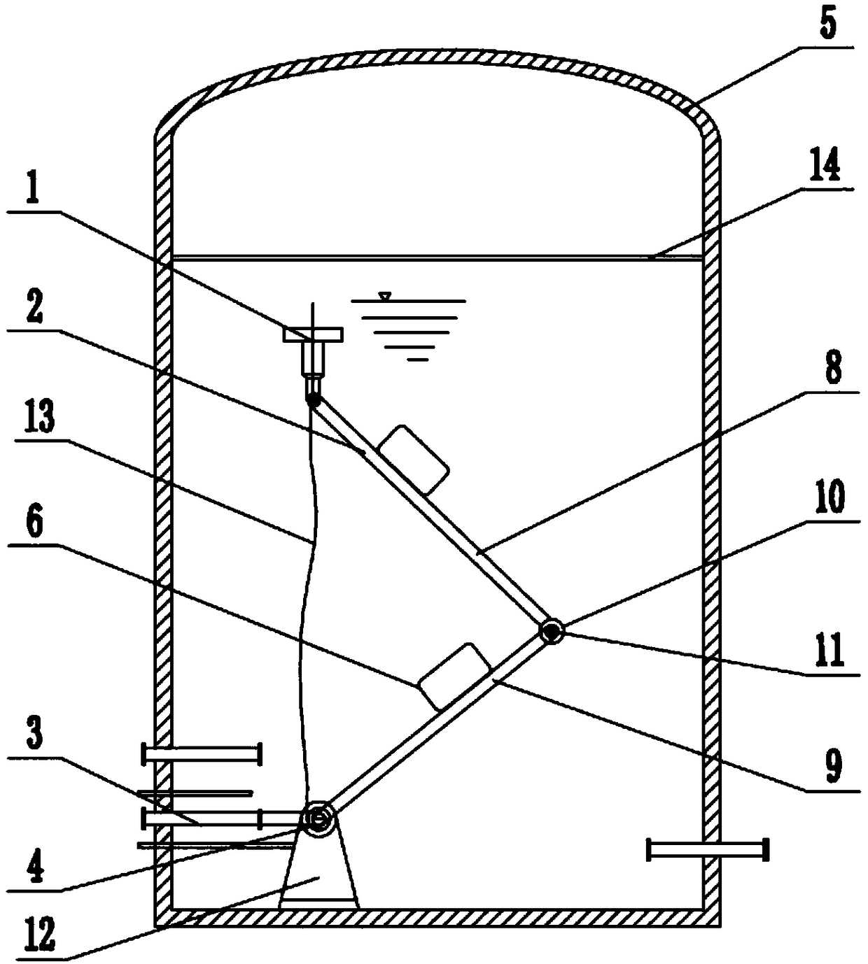
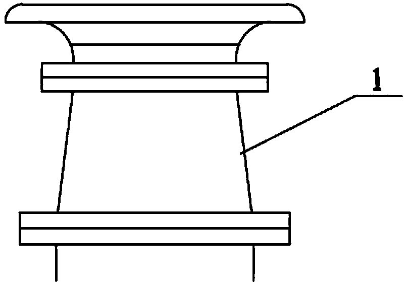
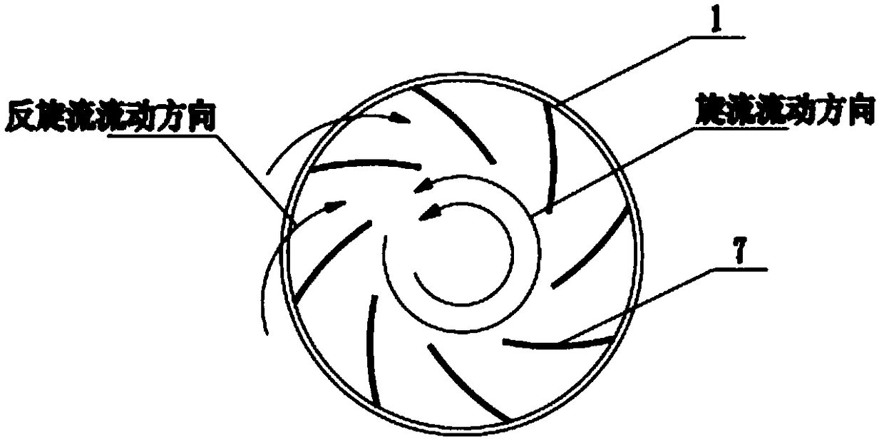
[0026] This embodiment provides a fluid suction device, such as Figure 1-3 As shown, it ...


PUM


Abstract

The invention discloses a fluid suction device. The fluid suction device comprises an oil suction port, an oil suction arm, an oil outlet pipe, a rolling device and a controller. The top end of the oil suction port is arranged at the bottom of the liquid face in an oil tank. The bottom end of the oil suction port is connected with the top end of the oil suction arm. The bottom end of the oil suction arm is connected with the oil outlet pipe. The rolling device is arranged between the oil suction arm and the oil outlet pipe. An arm body of the oil suction arm is further provided with a buoyancyoil barrel. The controller is connected with the rolling device and can control the rolling device to limit the position of the oil suction arm. According to the provided fluid suction device, the oil suction port is formed below the liquid face, an oil liquid suction-in port is arranged upwards, and the oil suction port is internally provided with a plurality of reverse rotational flow blades; and meanwhile, the rolling device and a rotation device are further arranged, and the beneficial effects that the oil suction efficiency is high, and the device stability is good are achieved.

Description

technical field [0001] The invention relates to the technical field of oil pumping equipment, in particular to a fluid pumping device. Background technique [0002] Fluid suction devices are mainly used in oil fields, refineries, gas stations, airports, aviation, smelting and other industries, and are suitable for installation and use of crude oil or product oil tanks; Suction arm with its suction port facing down. Since the oil suction port of the floating oil suction arm faces downward, once the gas enters the oil suction arm, it will destroy the balance generated by the buoyancy of the oil barrel, forming a violent upward buoyancy force, causing the suction port to break away from the liquid surface, making it impossible to absorb oil; at the same time, causing damage to the top floating plate, Large losses are generated; the suction port of the floating oil suction arm faces downward, once the gas enters the oil suction arm, the gas will be deposited in the upper elbow ...

Claims


Application Information

Patent Timeline
Patent Type & Authority Applications(China)
IPC IPC(8): B67D7/04B67D7/06
CPCB67D7/04B67D7/06
Inventor 李汉光
Owner 大连鸿泽泵业有限公司
Why Eureka
Try Eureka