
Automatic piling device for communication signal tower construction

A communication signal and piling equipment technology, which is applied in construction, sheet pile walls, and foundation structure engineering, etc., can solve the problems of manual hand injury, slow piling speed, low piling efficiency, etc., and achieve high piling efficiency. The effect of fast piling speed and high work efficiency

Inactive Publication Date: 2018-07-20
JINHUA MANGO INFORMATION TECH CO LTD
View PDF8 Cites 1 Cited by
  • Summary
  • Abstract
  • Description
  • Claims
  • Application Information

AI Technical Summary

Problems solved by technology

[0003] In order to solve the above-mentioned problems, the present invention provides an automatic piling device for the construction of communication signal towers, which can solve the problem of manual piling on slope protection in the construction of existing communication signal towers, extremely slow piling speed, and poor piling efficiency. It can realize the automatic piling function of the slope protection of the communication signal tower that can buffer the shock-absorbing and hammering force. It does not need manual operation and has high work efficiency. It also has automatic piling on the slope protection, fast piling speed and High piling efficiency and other advantages

Method used


Image

  • Automatic piling device for communication signal tower construction
  • Automatic piling device for communication signal tower construction
  • Automatic piling device for communication signal tower construction

Examples


Embodiment Construction

[0018] In order to make the technical means, creative features, goals and effects achieved by the present invention easy to understand, the present invention will be further described below in conjunction with specific illustrations.

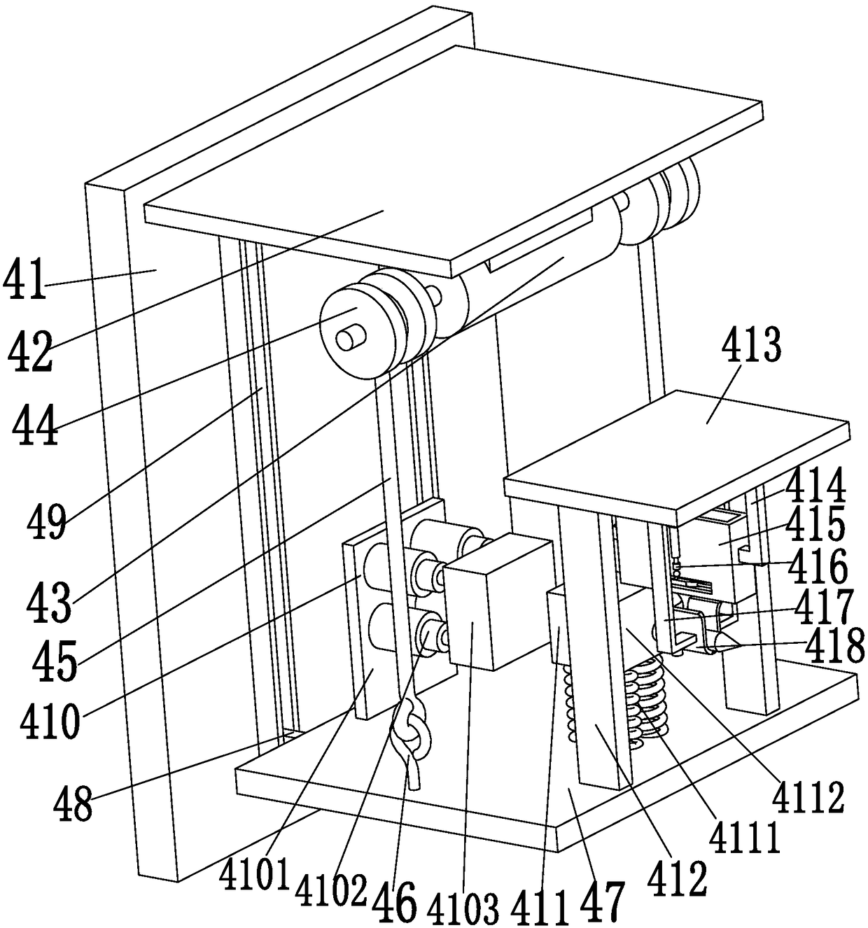
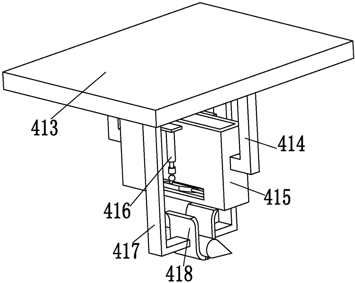
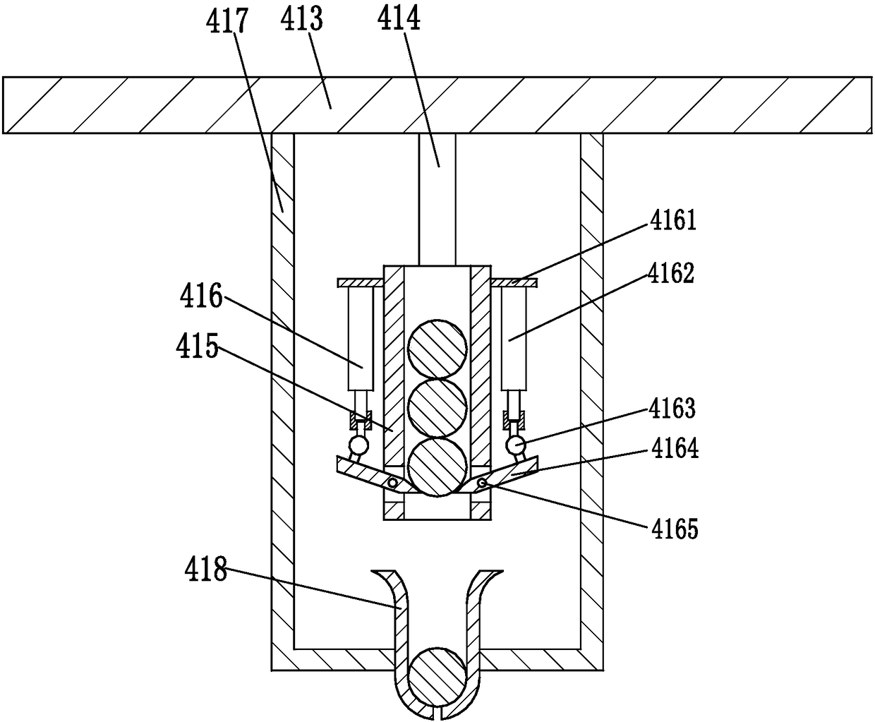
[0019] Such as Figure 1 to Figure 3As shown, an automatic piling device for the construction of a communication signal tower includes a piling support plate 41, a piling vertical plate 42 is installed on the front end surface of the piling support plate 41, and a bidirectional drive is installed on the lower side of the upper end surface of the piling vertical plate 42. Motor 43, two output shafts of bidirectional driving motor 43 are respectively equipped with a winding wheel 44, is wound with steel strand 45 on the winding wheel 44, and the lower end of steel strand 45 is fixed on the connecting hook 46, and connecting hook 46 is installed On the piling platform 47, the rear end of the piling platform 47 is symmetrically provided with piling ...


PUM


Abstract

The invention relates to an automatic piling device for communication signal tower construction. The automatic piling device for communication signal tower construction comprises a piling support plate, wherein a piling vertical plate is arranged on the upper side of the front end surface of the piling support plate; a bidirectional drive motor is arranged on the lower side of the upper end surface of the piling vertical plate; winding wheels are arranged on two output shafts of the bidirectional drive motor; steel strands are wound on the winding wheels; the lower ends of the steel strands are fixed onto a connecting hook; the connecting hook is arranged on a piling table; pilling support pillars are symmetrically arranged at the rear end of the piling table and are matched with piling sliding chutes to move; the piling sliding chutes are formed in the piling support plate; a reciprocating hammering mechanism is arranged on the rear side of the upper end surface of the piling table; and a damping and pushing mechanism is arranged in the middle of the upper end surface of the piling table. The automatic piling device for communication signal tower construction provided by the invention can solve the problems that according to an existing protection slope piling process method during communication signal tower construction, piles are manually driven in a protection slope, the piling speed is low, the piling efficiency is low, the hands of workers are easy to hurt by vibration, and the like.

Description

technical field [0001] The invention relates to the technical field of communication signal tower construction, in particular to an automatic piling device for communication signal tower construction. Background technique [0002] Communication signal towers such as mobile, telecommunications, and China Unicom are often seen. Due to the radiation of these communication signals, they are generally set on high mountains far away from urban residential areas. In order to prevent natural disasters such as mudslides, landslides, and rolling stones from causing damage Influence, the upper slope protection is usually set up around the communication signal tower. At present, the construction of the communication signal tower slope protection on the high mountain mainly includes the following steps: the first step, choose a slightly flat place surrounded by slope walls as the communication signal tower The construction site, and then manually trim and clean the dead branches and vine...

Claims


Application Information

Patent Timeline
Patent Type & Authority Applications(China)
IPC IPC(8): E02D27/42E02D7/08
CPCE02D27/42E02D7/08
Inventor 马双斌
Owner JINHUA MANGO INFORMATION TECH CO LTD
Learn More