Optical signal positioning device, method and system

A positioning device and optical signal technology, applied in the field of photoelectric signals, can solve the problems of high power consumption, limited application range, inability to save energy, etc., and achieve the effect of power consumption

Inactive Publication Date: 2018-07-20
张斌
View PDF10 Cites 1 Cited by
  • Summary
  • Abstract
  • Description
  • Claims
  • Application Information

AI Technical Summary

Problems solved by technology

Although RFID has high positioning accuracy, since RFID needs to be identified by induction to achieve positioning, it can only be applied to short-distance positioning, so its application range is greatly limited.
Furthermore, in precise positioning, whether it is RFID or other technologies, its power consumption is relatively high, and energy saving cannot be achieved.

Method used


Image

  • Optical signal positioning device, method and system
  • Optical signal positioning device, method and system
  • Optical signal positioning device, method and system

Examples


no. 1 example

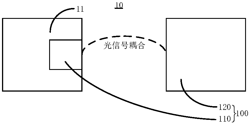
[0031] see figure 1 , the first embodiment of the present invention provides an optical signal locating system 10 , the optical signal locating system 10 includes: an object under test 11 and an optical signal locating device 100 .

[0032] The object to be tested 11 may be an object that needs to be tracked, and it may be, for example, a person, an animal, a drone, and the like. The optical signal sending module 110 in the optical signal locating device 100 can be installed on the object under test 11 . When the optical signal sending module 110 in the optical signal sending module 110 sends the positioning light and at least two flashing lights, the optical signal processing module 120 in the optical signal sending module 110 correspondingly collects the positioning light and at least two flashing lights, And according to the positioning light and at least two flashing lights, the position change of the object under test 11 is determined, thereby realizing long-distance pre...

no. 2 example

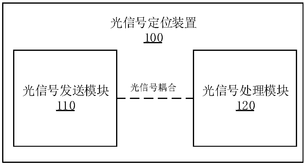
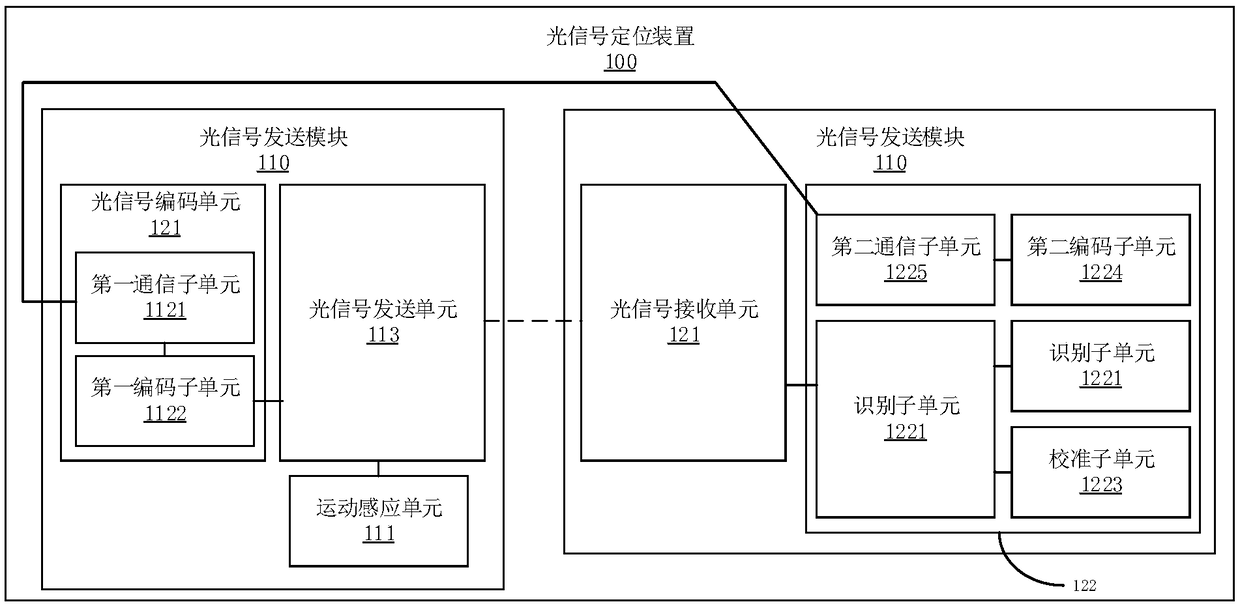
[0034] see figure 2 , the second embodiment of the present invention provides an optical signal locating device 100 , the optical signal locating device 100 includes: an optical signal sending module 110 and an optical signal processing module 120 . Wherein, the optical signal sending module 110 and the optical signal processing module 120 are optically coupled, and the optical signal sending module 110 is used for installing on the object under test 11 .

[0035] The optical signal sending module 110 is used for judging whether the moving speed of the object under test 11 satisfies a preset condition, and if yes, emits positioning light through the positioning light source 1131 and emits flashing light through at least two light sources 1132 .

[0036] The optical signal processing module 120 is used to obtain the positioning information of the object under test 11 according to the collected positioning light, and determine the position change of the object under test 11 acc...

no. 3 example

[0083] see Figure 8 , the third embodiment of the present invention provides an optical signal locating method, the method is applied to an optical signal locating device, and the method includes:

[0084] Step S100: The optical signal sending module judges whether the moving speed of the object under test satisfies a preset condition, and if yes, emits positioning light through a positioning light source, and emits flashing light through at least two light sources.

[0085] Step S200: The optical signal processing module obtains the positioning information of the object under test according to the collected positioning light, and determines the position change of the object under test according to the collected at least two flashing lights and the positioning information Condition.

[0086] see Figure 9 , the third embodiment of the present invention provides an optical signal positioning method, step S100 includes:

[0087] Step S110: The optical signal sending module j...


PUM


Abstract

The invention provides an optical signal positioning device, a method and a system and belongs to the photoelectric signal technology field. The device comprises an optical signal sending module and an optical signal processing module. The optical signal sending module and the optical signal processing module form optical coupling. The optical signal sending module is installed on an object to bemeasured. The optical signal sending module is used for determining whether the moving speed of the object to be measured satisfies a preset condition. If the moving speed of the object to be measuredsatisfies the preset condition, through positioning a light source, positioning light is emitted, and through at least two light sources, flare light is emitted. The optical signal processing moduleis used for acquiring the positioning information of the object to be measured according to the collected poisoning light and determining the position change condition of the object to be measured according to the at least two paths of collected flare light and the positioning information. The optical signal sending module emits the flare light according to the moving speed so as to realize the control of power consumption. The optical signal processing module collects the flare light sent by the optical signal sending module on the object to be measured so that the object to be measured is accurately identified, positioned and tracked in middle and long distances.

Description

technical field [0001] The present invention relates to the field of photoelectric signal technology, in particular to an optical signal positioning device, method and system. Background technique [0002] With the development and progress of science and technology, the technology of positioning the object to be measured has been widely used in society. [0003] Currently, a GPS-installed object to be measured can be positioned through a GPS (Global Positioning System, Global Positioning System). Although GPS positioning can realize long-distance positioning, there is a technical problem that the positioning is not accurate enough. In addition, at present, RFID (Radio Frequency Identification, radio frequency identification) can also be used to locate the object under test installed with RFID. Although RFID has high positioning accuracy, it can only be applied to short-distance positioning because RFID needs to be identified by induction to achieve positioning, so its appl...

Claims


Application Information

Patent Timeline
IPC IPC(8): G01S5/16
CPCG01S5/16G01S1/70
Inventor 张斌
Owner 张斌
Why Eureka
Try Eureka