
Timekeeper

A clock and mode technology, applied in the field of clocks and watches, can solve the problems of increasing the structural parts of clocks and clocks, impairing the miniaturization of clocks, and achieving the effect of restraining the enlargement of the clocks.

Inactive Publication Date: 2018-07-20
SEIKO INSTR INC
View PDF1 Cites 4 Cited by
  • Summary
  • Abstract
  • Description
  • Claims
  • Application Information

AI Technical Summary

Problems solved by technology

Therefore, a driving source such as a motor for separately driving the two chronograph hands and a wheel train for transmitting the driving force of the driving source are also required, so the number of structural parts of the timepiece increases, which may impair the miniaturization of the timepiece.

Method used


Image

  • Timekeeper
  • Timekeeper
  • Timekeeper

Examples


no. 1 approach

[0047] First, the structure of the timepiece of the first embodiment will be described.

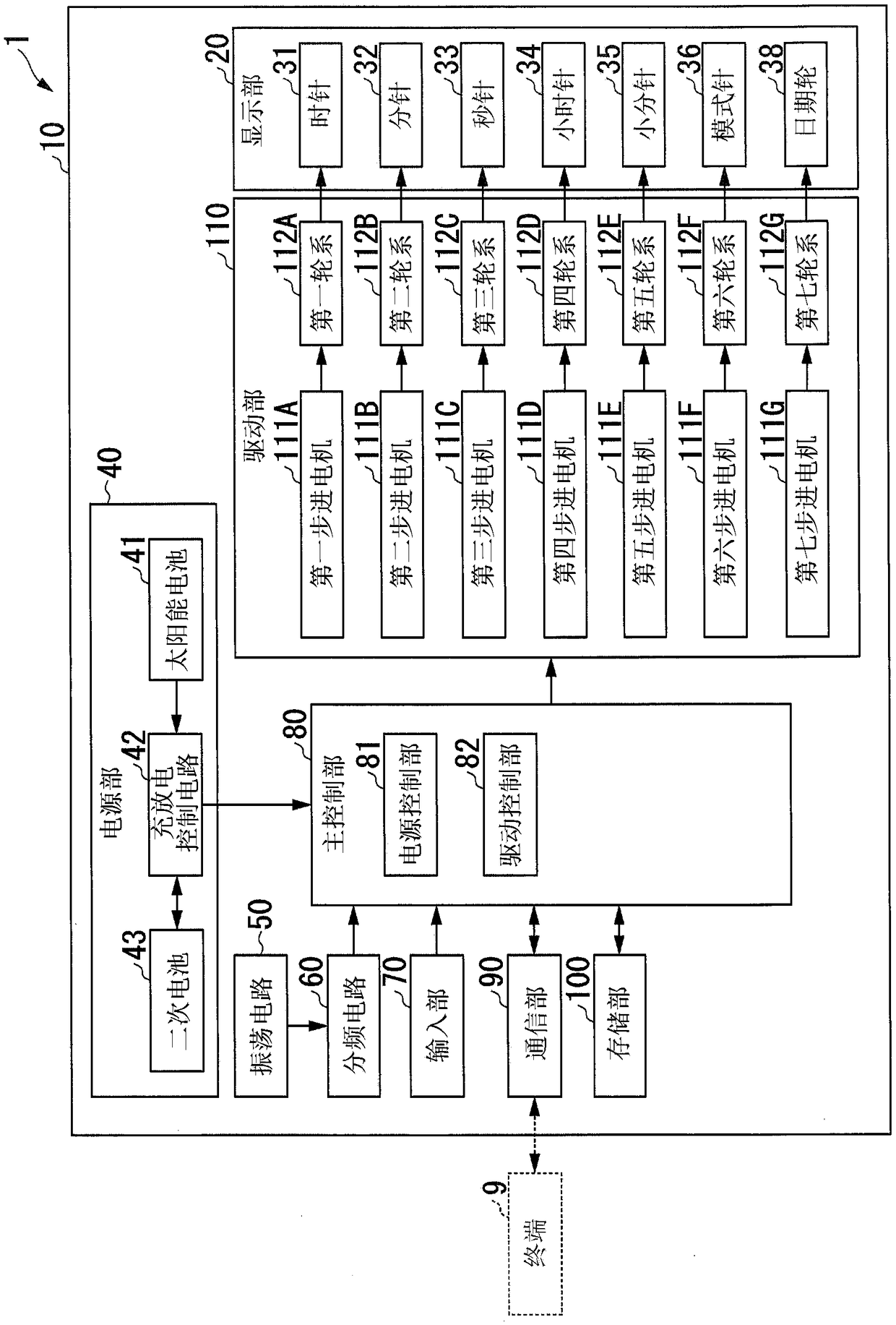
[0048] figure 1 It is a block diagram showing a configuration example of the timepiece of the first embodiment.

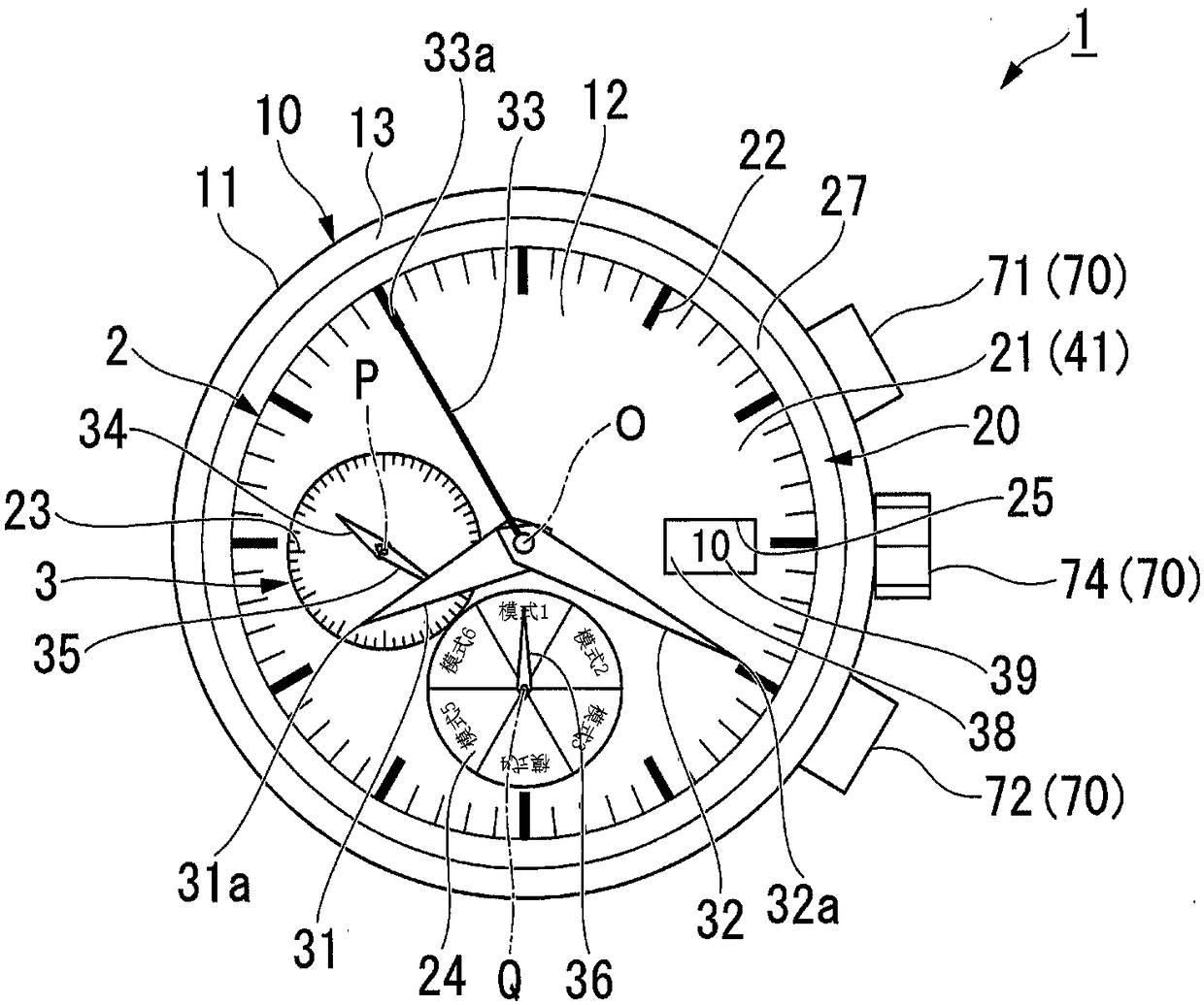
[0049] like figure 1 As shown, the timepiece 1 has a case 10, a display unit 20, a power supply unit 40, an oscillation circuit 50, a frequency division circuit 60, an input unit 70, a main control unit 80 (control unit), a communication unit 90, a storage unit 100, and a drive unit 110. . The timepiece 1 can select a timepiece mode in which the current time is displayed in the main timepiece part 2 described later, a chronograph mode in which the time is measured in the main timepiece part 2, a timer mode in which the remaining time is displayed in the main timepiece part 2, and a preset The current time in the set time zone is displayed on the main clock part 2 in an operation mode such as a dual time mode. The operation mode is selected by the user operating the input u...

no. 2 approach

[0176] Next, the operation of the timepiece of the second embodiment will be described.

[0177] Figure 16 It is a flowchart showing the processing flow of the timekeeping mode executed by the timepiece of the second embodiment.

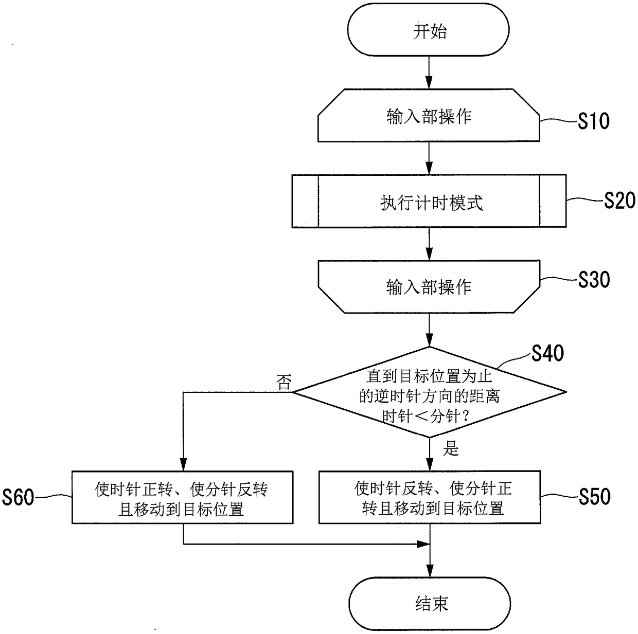
[0178] exist image 3 and Figure 5 In the first embodiment shown, when the input unit 70 (such as the crown 74) is operated (step S10), the main control unit 80 moves the hour hand 31, the minute hand 32, and the second hand 33 to the reference position (step S10). S304, step S306), when the start / stop button 71 is further operated (S104: Yes), time measurement is started. In contrast, in Figure 16 The second embodiment shown differs from the first embodiment in that when the input unit 70 (for example, the start / stop button 71) is operated (step S10), the main control unit 80 makes the hour hand 31. The minute hand 32 and the second hand 33 move toward the reference position and start time measurement (step S202). In addition, about the sam...


PUM


Abstract

The invention provides a timekeeper which can restrain large size of a device. A timekeeper (1) can select a timekeeper mode and a timekeeping mode. The timekeeper has a hour pointer (31) and a minutehand (32) which indicate time under the condition that the timekeeper mode is selected, and a main control portion which is controlled to start time measurement through starting pointer movement of the hour pointer (31) and the minute hand (32) at the same time, and measured time when pointer movement of the hour pointer (31) is stopped is indicated. Time measurement is continued through pointermovement of the minute hand (32).

Description

technical field [0001] The present invention relates to timepieces. Background technique [0002] An electronic timepiece capable of measuring split time or lap time by button operation. For example, Patent Document 1 describes a digital timepiece as a stopwatch having a display unit for displaying elapsed time from the start of operation, lap time, and split time. In addition, the split time refers to the elapsed time from the start of the measurement, and the lap time refers to the elapsed time from the designated point in the middle of the measurement. [0003] And, as an analog timepiece capable of measuring divided times, there is a structure in which a hand that starts moving during time measurement is stopped by a button operation for measuring divided times, thereby indicating divided times. However, in such timepieces, the movement of the hands is stopped in order to display the divided time, so the elapsed time from the start of measurement cannot be recognized a...

Claims


Application Information

Patent Timeline
Patent Type & Authority Applications(China)
IPC IPC(8): G04C3/14
CPCG04C3/14
Inventor 酒井聪井桥朋宽
Owner SEIKO INSTR INC
Learn More