
A small-inertia auto-rotation control method and system for a space remote sensing scanning imaging system

A technology of scanning imaging and control methods, which can be used in adaptive control, general control systems, control/regulation systems, etc., and can solve problems such as torque interference

Active Publication Date: 2020-11-10
BEIJING RES INST OF SPATIAL MECHANICAL & ELECTRICAL TECH
View PDF5 Cites 0 Cited by
  • Summary
  • Abstract
  • Description
  • Claims
  • Application Information

AI Technical Summary

Problems solved by technology

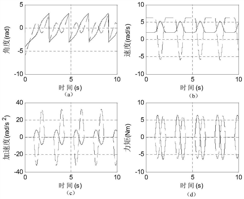
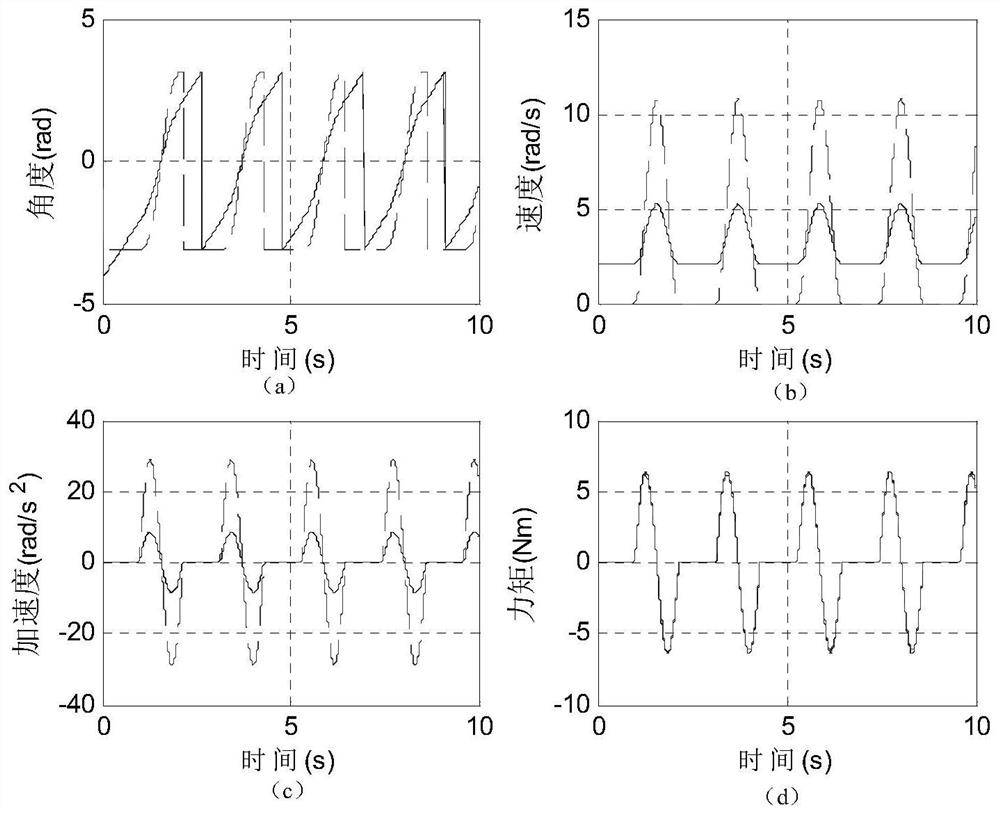
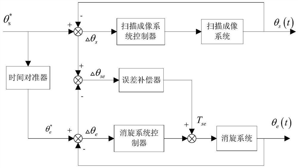
[0003] The technical problem solved by the present invention is: Aiming at the moment interference problem of the large inertia space remote sensor to the satellite platform, a small inertia self-despinning control method and system for the space remote sensing scanning imaging system are proposed to reduce the space volume of the remote sensor load In the process of error compensation, a time aligner is introduced to achieve synchronous control, combined with the design of the driving mechanism, to ensure that the small inertia derotation system and the scanning imaging system maintain the same moment and opposite direction at the corresponding time, so that the overall load acts on the satellite. The comprehensive disturbance torque on the platform meets the index requirements

Method used


Image

  • A small-inertia auto-rotation control method and system for a space remote sensing scanning imaging system
  • A small-inertia auto-rotation control method and system for a space remote sensing scanning imaging system
  • A small-inertia auto-rotation control method and system for a space remote sensing scanning imaging system

Examples


Embodiment Construction

[0047] The working principle and working process of the present invention will be further explained and illustrated below in conjunction with the accompanying drawings.

[0048] The kinematic characteristics of the scanning imaging system are known, including the angular position command curve and the moment of inertia. Wherein, the angular position command curve includes: the motion curve of the constant speed segment, the motion curve of the shift segment, the time of the constant speed segment, the time of the shift segment and the motion form of the shift segment. During the motion of the scanning imaging system, only the variable speed section will generate torque interference to the satellite. Therefore, the derotation system needs to ensure that the torque of the scanning imaging system is the same at each moment and the torque direction is opposite in the variable speed section of the scanning imaging system. According to the characteristics of the scanning imaging sys...


PUM


Abstract

The invention relates to a small inertia self-rotation-eliminating control method and system for a spatial remote-sensing scanning imaging system. The method comprises: step one, planning a motion curve of a rotation eliminating system; step two, optimizing a rotation inertia of the rotation eliminating system; step three, setting a time aligner and acquiring a rotation eliminating system angularposition theta <*>e at a same time of a scanning imaging system; step four, setting an error compensator output Tse; and step five, planning a motion curve of the rotation eliminating system by usingrotation eliminating system rotation inertia minimization as an objective, introducing error compensation Tse by using the rotation eliminating system angular position theta <*>e calibrated by the time aligner as a control input, and carrying out rotation eliminating controlling on the scanning imaging system. Therefore, the rotation inertia of the rotation eliminating system is minimized while the index requirement is met. When the rotation inertia of the rotation eliminating system is reduced, the motion characteristics change subsequently; on the basis of implementability of the mechanism design, the motion characteristics and the rotation inertia of the rotation eliminating system are optimized, so that the interference torque of the scanning imaging system is cancelled by the small inertia rotation eliminating system.

Description

technical field [0001] The invention belongs to the field of remote sensor control, and relates to a small-inertia auto-despin control method and system for a space remote sensing scanning imaging system. Background technique [0002] With the expansion of the observation range of space remote sensing cameras and the improvement of index requirements, the structural size of the scanning imaging system is also increasing, which leads to a corresponding increase in the disturbance of the scanning imaging system to the satellite. For the satellite platform, the disturbance moment from the load belongs to the external disturbance source. In order to ensure the attitude stability of the satellite platform, it is necessary to deeply analyze the characteristics and changing laws of external interference in order to effectively suppress it. Considering the overall design idea for payload products, as well as the comprehensiveness of the internal characteristic analysis of the paylo...

Claims


Application Information

Patent Timeline
Patent Type & Authority Patents(China)
IPC IPC(8): G05B13/04
CPCG05B13/042
Inventor 迟冬南王庆颖徐丽娜贾慧丽张秀茜凌龙吴南
Owner BEIJING RES INST OF SPATIAL MECHANICAL & ELECTRICAL TECH
Learn More