

Magnetic circuit structure design method under long service life design of magnetic focusing Hall thruster
A Hall thruster and magnetic focusing technology, which is applied in reducing greenhouse gases, nuclear power generation, electrical components, etc., can solve problems such as changes in magnetic field parameters and reduced excitation efficiency
- Summary
- Abstract
- Description
- Claims
- Application Information
AI Technical Summary
Problems solved by technology
Method used
Image

Examples
Embodiment 1
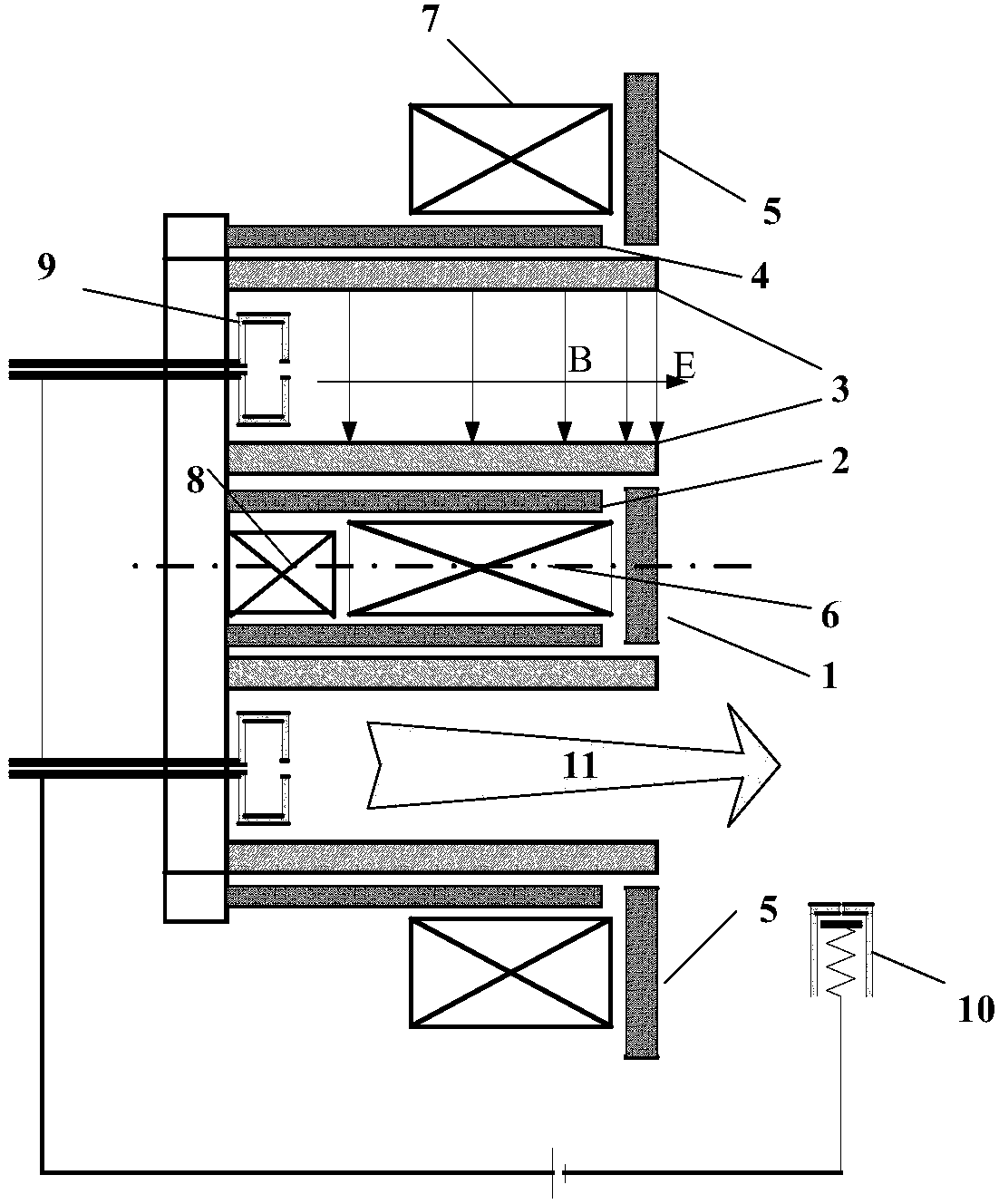
[0038] A magnetic circuit structure design method under the long-life design of a magnetically focused Hall thruster, the method is: first, the wall thickness of the ceramic discharge channel, the thickness of the inner magnetic screen and the outer magnetic screen are all increased to the original thickness of each component 2 times, and then adjust the rear section of the ceramic discharge channel wall to a segmented structure or reduce the thickness of the ceramic discharge channel wall at the rear section of the ceramic discharge channel, and finally reduce the loss of excitation efficiency.
[0039] The concrete steps of described method comprise:
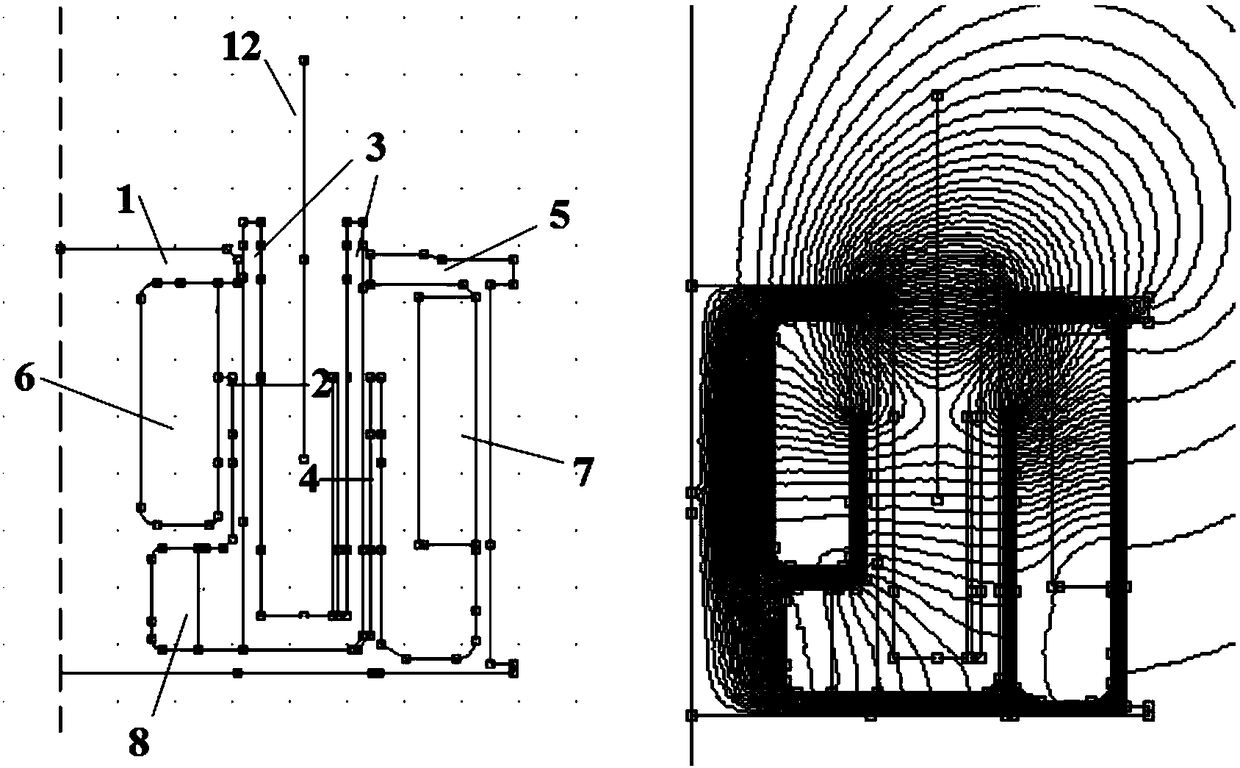
[0040] Step 1: If figure 2 with image 3 As shown, the HET-100 Hall thruster magnetic circuit structure increases the wall thickness of the ceramic discharge channel from 3mm to 6mm;
[0041] Step 2: Use ferrite materials to make the inner and outer magnetic shields of the magnetically focused Hall thruster to prevent magne...
Embodiment 2
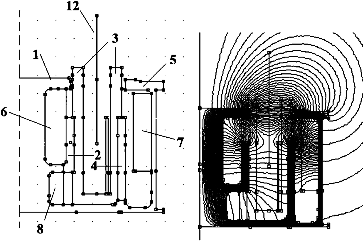
[0049] A magnetic circuit structure design method under the long-life design of a magnetically focused Hall thruster, the method is: first, the wall thickness of the ceramic discharge channel, the thickness of the inner magnetic screen and the outer magnetic screen are all increased to the original thickness of each component 2 times, and then adjust the rear section of the ceramic discharge channel wall to a segmented structure or reduce the thickness of the ceramic discharge channel wall at the rear section of the ceramic discharge channel, and finally reduce the loss of excitation efficiency. The concrete steps of described method comprise:
[0050] Step 1: increasing the wall thickness of the ceramic discharge channel from 3mm to 6mm;
[0051] Step 2: Use ferrite materials to make the inner and outer magnetic shields of the magnetically focused Hall thruster to prevent magnetic saturation; and increase the thickness of the inner and outer magnetic shields to 2 times their ...
PUM
| Property | Measurement | Unit |
|---|---|---|
| Wall thickness | aaaaa | aaaaa |
| Thickness | aaaaa | aaaaa |
| Thickness | aaaaa | aaaaa |
Abstract
Description
Claims
Application Information