
Low-pressure casting molten metal feeding method

A low-pressure casting and molten metal technology, which is applied in the field of low-pressure casting, can solve problems such as product cold barrier defects, increase production costs, and product process design limitations, and achieve the effects of reducing the probability of cold barrier defects, preventing condensation, and facilitating reflux

Inactive Publication Date: 2018-07-24
SUZHOU TORIN MACHINERY CASTING
View PDF18 Cites 1 Cited by
  • Summary
  • Abstract
  • Description
  • Claims
  • Application Information

AI Technical Summary

Problems solved by technology

[0005] (1) The gate of the mold is directly in contact with the riser pipe. Since the position of the riser pipe cannot be changed on the low-pressure holding furnace, the gate must be aligned with the riser pipe during product design, which has great limitations for product process design; Sometimes two or three risers are used on the low-pressure holding furnace. In addition to the position of the gate, the position of the gate must be considered in the product design of this method. Since the low-pressure hot air acts on the liquid surface of the low-pressure holding furnace, the three gates are left out. The pressure of the aluminum liquid varies, which will lead to cold insulation defects in the product;
[0006] (2) A shunt bag is used between the riser and the gate. This method breaks through the problem of fixed gate position during product design, but often due to unreasonable design, aluminum liquid condenses in the shunt bag and seriously affects the product. Production beats; ceramic materials are also used as shunt bags, but this will greatly increase production costs

Method used


Image

  • Low-pressure casting molten metal feeding method

Examples


Embodiment Construction

[0029] In order to make the above objects, features and advantages of the present application more clearly understood, the specific embodiments of the present application will be described in detail below with reference to the accompanying drawings. In the following description, numerous specific details are set forth in order to provide a thorough understanding of the present application. However, the present application can be implemented in many other ways different from those described herein, and those skilled in the art can make similar improvements without departing from the connotation of the present application. Therefore, the present application is not limited by the specific embodiments disclosed below.

[0030] In the description of this application, it should be understood that the terms "center", "longitudinal", "lateral", "length", "width", "thickness", "upper", "lower", "front", " Back, Left, Right, Vertical, Horizontal, Top, Bottom, Inner, Outer, Clockwise, Co...


PUM


Abstract

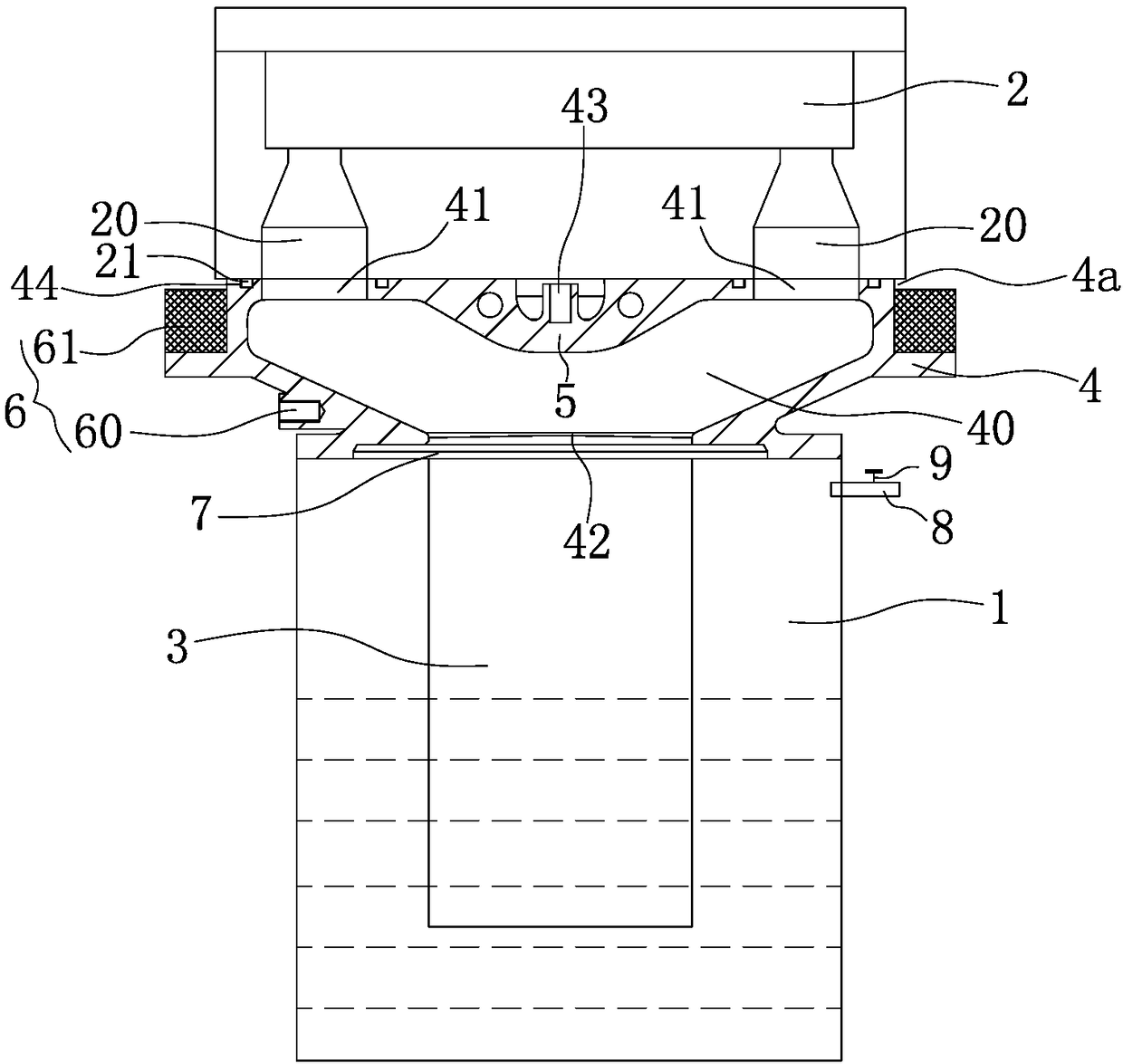
The invention discloses a low-pressure casting molten metal feeding method. A molten metal feeding system adopted for the method comprises a molten metal storage tank and a lift tube, wherein the upper end of the lift tube is connected with a plurality of sprues of a mold cavity, and the lower end of the lift tube extends into molten metal. The molten metal feeding system comprises a liquid lift box, a flow distribution assembly and a temperature control assembly, wherein the liquid lift box is provided with first connectors and a second connector connected with the sprues and the upper end ofthe lift tube correspondingly; a flow distribution assembly is arranged in an inner cavity and used for distributing molten metal going into the inner cavity to each first connector; the temperaturecontrol assembly is arranged on the liquid lift box and can conduct constant-temperature treatment on the molten metal in the liquid lift box; the first connectors are distributed on the top of the liquid lift box with the center of the flow distribution assembly as the circle center in the circumferential direction of the liquid lift box. On one hand, the molten metal feeding system only needs one lift tube; under the flow distribution effect of the flow distribution assembly, the molten metal uniformly flows to the sprues, and the probability of cold shut defects occurring to products is reduced. On the other hand, the molten metal is prevented from condensing through the temperature control assembly, and it is guaranteed that castings are solidified and molded at low pressure all the time.

Description

technical field [0001] The invention belongs to the field of low-pressure casting, and particularly relates to a liquid metal supply method for low-pressure casting. Background technique [0002] Low pressure casting is a casting method in which liquid alloys are pressed into the mold cavity from bottom to top under pressure, and solidified under pressure to obtain castings. [0003] The specific principle is: the gas above the molten metal generates pressure on the molten metal, so that the molten metal can smoothly fill the mold from bottom to top through the runner along the liquid riser, and the filling pressure is generally 20-60kPa. When the casting is completely solidified, the gas pressure on the liquid surface is released, so that the unsolidified metal liquid in the riser and the runner flows into the crucible by its own weight, and then the mold is opened and the casting is taken out. [0004] However, at this stage, there are two ways to connect the low-pressure...

Claims


Application Information

Patent Timeline
Patent Type & Authority Applications(China)
IPC IPC(8): B22D18/04B22D18/08
CPCB22D18/04B22D18/08
Inventor 张伟峰钱晨晖周鹏
Owner SUZHOU TORIN MACHINERY CASTING
Learn More