Pipe cutting device

A cutting device and pipe technology, applied in metal processing, cleaning methods and appliances, chemical instruments and methods, etc., can solve problems such as inability to fix pipes, lack of powder collection, uneven incisions, etc.

Inactive Publication Date: 2018-07-24
李耀强
View PDF0 Cites 2 Cited by
  • Summary
  • Abstract
  • Description
  • Claims
  • Application Information

AI Technical Summary

Problems solved by technology

[0002] In indoor hydropower installation, the lines are wrapped inside the pipes, which is beneficial to protect the lines and avoid corrosion of the lines. Therefore, it is necessary to cut the pipes to make the pipes suitable for the indoor space layout. The existing pipe cutting devices are not With the function of powder collection, the waste generated by cutting is accumulated indoors, requiring personnel to clean it, which is time-consuming and labor-intensive. In addition, when cutting pipes, the existing device cannot fix the pipes, resulting in cuts during cutting Uneven

Method used


Image

  • Pipe cutting device
  • Pipe cutting device
  • Pipe cutting device

Examples


Embodiment Construction

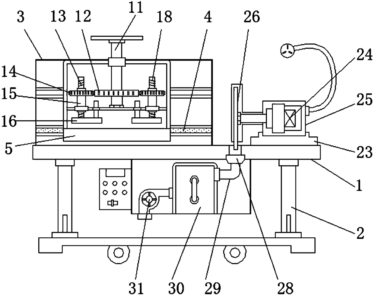
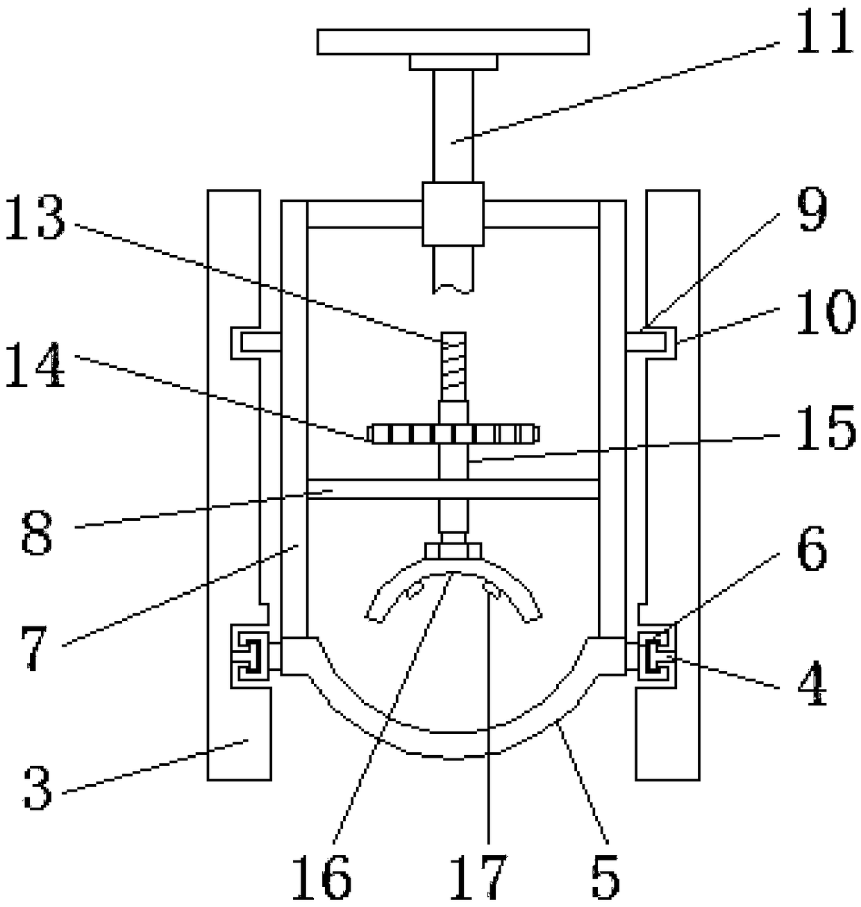
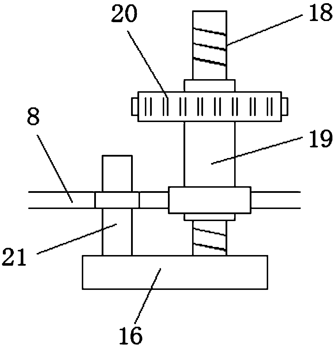
[0018] like Figure 1-Figure 5 As shown, a pipe cutting device mainly includes a support table 1, a moving frame 2, a protective baffle 3, a first slide rail 4, a supporting plate 5, a first slider 6, a fixed cover 7, an isolation plate 8, a second The second slider 9, the second slide rail 10, the hand wheel 11, the transmission gear 12, the first screw rod 13, the first moving gear 14, the first lifting sleeve 15, the limit pressure plate 16, the fixed convex strip 17, the first Two screw mandrels 18, the second lifting sleeve 19, the second moving gear 20, the limit rod 21, the safety cover 22, the load-bearing track 23, the motor 24, the mounting seat 25, the cutting knife 26, the limit groove 27, the suction Tuyere 28, air duct 29, ash collection box 30 and axial flow fan 31, mobile frame 2 is installed below the support table 1, and protective baffle 3 is fixed on the top of mobile frame 2, and the inner wall of protective baffle 3 is provided with The first slide rail ...


PUM


Abstract

The invention discloses a pipe cutting device. The pipe cutting device mainly comprises a support table surface, a bearing plate, a hand wheel, a motor and an air conveying pipe. The pipe cutting device is characterized in that a moving frame is installed below the support table surface; a first lifting sleeve and a second lifting sleeve penetrate through the surface of an isolation plate separately, and a first screw rod is connected in the first lifting sleeve; a first secondary movable gear is arranged on the outer surface of the first lifting sleeve; the upper end of the air conveying pipeis mutually connected with an air suction port, and the left end of the air conveying pipe is connected with an ash collection box in a penetrating manner; and the left side of the ash collection boxis mutually connected with the air suction port of an axial-flow fan. According to the pipe cutting device, the bearing plate with an arc-shaped structure is capable of bearing a pipe; a limit pressplate fixes the pipe, and prevents the pipe from being displaced due to instability in a cutting process; and the powder during cutting is sucked away by the axial-flow fan, and prevented from being accumulated on the support table surface.

Description

technical field [0001] The technical field of decoration equipment of the present invention is specifically a pipe cutting device. Background technique [0002] In indoor hydropower installation, the lines are wrapped inside the pipes, which is beneficial to protect the lines and avoid corrosion of the lines. Therefore, it is necessary to cut the pipes to make the pipes suitable for the indoor space layout. The existing pipe cutting devices are not With the function of powder collection, the waste generated by cutting is accumulated indoors, requiring personnel to clean it, which is time-consuming and labor-intensive. In addition, when cutting pipes, the existing device cannot fix the pipes, resulting in cuts during cutting Uneven. Contents of the invention [0003] The object of the present invention is to provide a pipe cutting device with the function of powder collection. [0004] The technical solution of the present invention is: a pipe cutting device, which mainly...

Claims


Application Information

Patent Timeline
IPC IPC(8): B26D7/02B26D7/18B08B5/04
CPCB26D7/02B08B5/04B26D7/1863
Inventor 李耀强
Owner 李耀强
Why Eureka
Try Eureka